Chapter One
Introduction
Man_455U-D Rev 3.07
Page
15
Because of radio start-up delays, the effective radio data rate will be lower than the transmitted
data rate. If you are sending large blocks of data, and the serial rate is equal or more than the
radio rate, we recommend that you use CTS/RTS flow control to prevent the input buffer from
overflowing.
1.5.1 PLC-Mode
The 455U-D will operate most efficiently when the serial data rate is higher or the same as the
radio data rate. If the serial data rate is less than the radio rate, there is a risk that the radio
will empty the input buffer too quickly, resulting in a single input message being broken into
more than one output messages. Many host protocols such as those used by PLC’s, will not
accept a message being broken into sections with delays between the sub-sections.
To avoid this occurring, the 455U-D will automatically delay the radio transmission starting if
the serial rate is less than the radio rate. This is called “PLC Mode”. The radio will not start
transmitting until a certain number of bytes have been input into the input buffer. The 455U-
D calculates the number of starting bytes depending on the values of the configured serial and
radio rates. The number of bytes to start transmitting is stored in register S18 (S20 for RS485))
- when a configuration is entered whereby the serial rate is less than the radio rate, the 455U
configuration software will automatically enter an appropriate value in S18. The user can
change this value. If the serial rate is the same as the radio rate, or more, than there is no
delay.
There is an automatic protection - if a certain time has elapsed and the number of starting
bytes has not been input, then the radio will start transmitting. This is an override protection.
The 455U-D will automatically calculate the override time based on the configured serial rate
and S18 (the number of bytes required to start). The override time is stored in register S19
(S21 for RS485) - this value can also be changed by the user.
In applications where the extra delay introduced by buffering data at the sending modem is
unacceptable, an alternative is to configure a “Transmitter Hold up” time (S-Register S27).
This keeps the transmission keyed up between data characters.
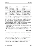
1.5.2 Character Type
The 455U-D may be configured by the user to
recognize the following types of characters - 7 or 8
data bits, even or odd or no parity, 1 or 2 stop bits.
Most applications will require the character type to be
the same at each 455U-D modem in the system.
Nevertheless, the character type may be configured to
be different at different 455U-D modems. Data is
transmitted by radio as an eight-bit byte without stop
or start bits. If the input data is 7 data bits, then the
byte transmitted by radio comprises the 7 bits plus a zero bit. Input characters with 8 bits are
transmitted as just the 8 data bits, with no parity. Because the data is transmitted without
parity, the user may configure CRC error checking to be added to each transmitted data packet.
Data is output at the destination module based on the character type configured at that module
- that is, the start/stop bits and parity is added to the radio data.
Data
Parity
Stop
7
Even
1
2
Odd
1
2
None
2
8
Even
1
Odd
1
None
1
2


