Instruction Book
Effective: November 2017 Page 26
For more information visit:
www.Eaton.com
IB131016EN
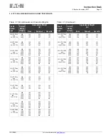
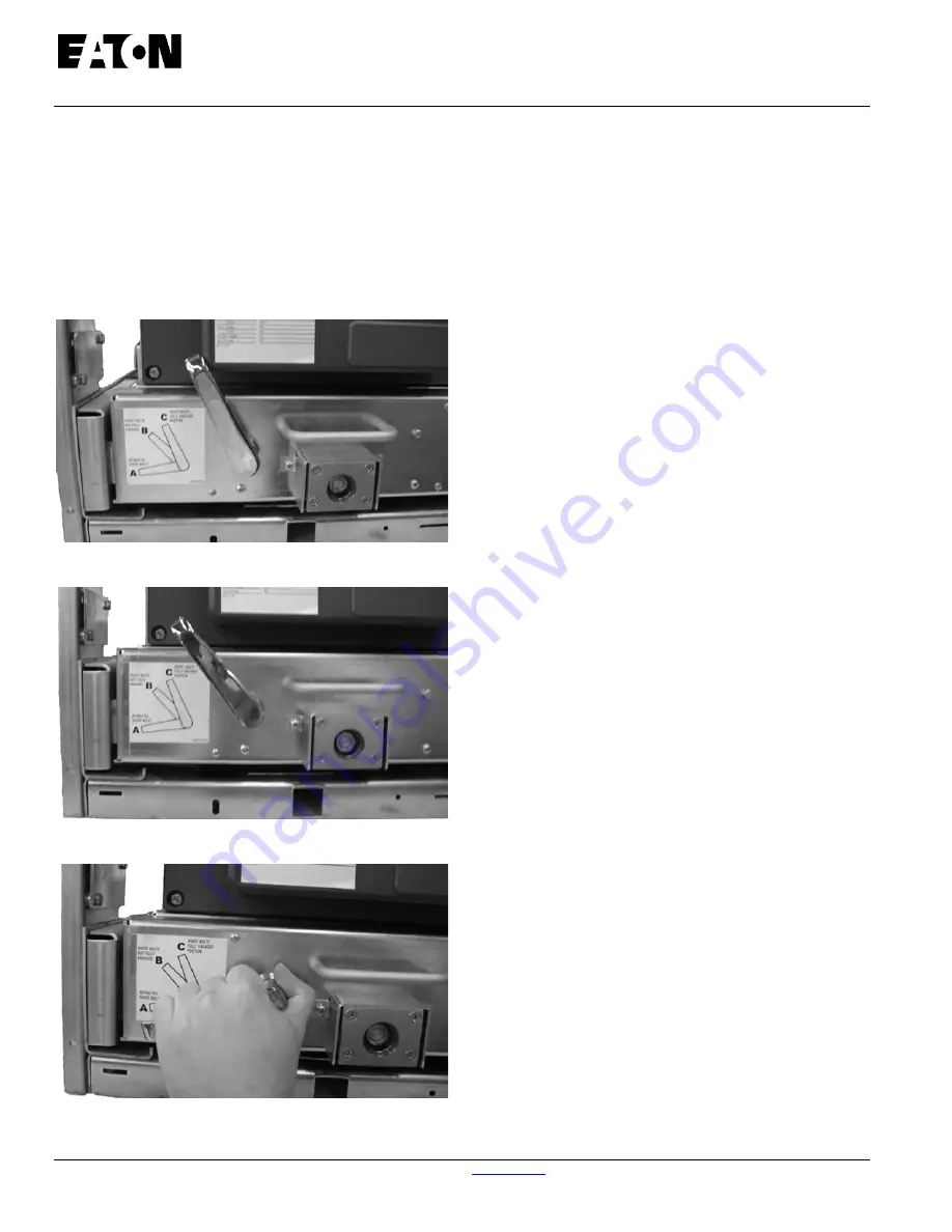
The circuit breaker and cassette are designed such that the
lower portion of the circuit breaker (the cradle) is held in the
DISCONNECT/TEST position by two shoot bolts which fit into
the rectangular slots of interlock plates located on each side of
the cassette’s frame. The shoot bolt handle can be in either
Position “B” (partially engaged) or Position “A” (not engaged)
for the breaker to be in the DISCONNECT position. The shoot
bolt handle
must,
however, be in Position “C” (fully engaged)
to be the TEST position and before the circuit breaker can be
levered to the CONNECTED position as dictated by the
design’s mechanical interlocking system.
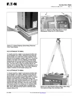
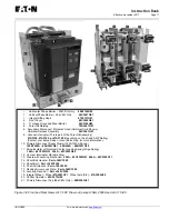
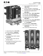
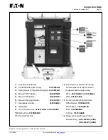
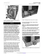
Figure 4-7 Shoot Bolt Handle Shown in Position “C” -
Shoot Bolts Protrude Fully From Cradle
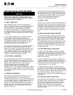
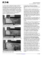
Figure 4-8 Shoot Bolt Handle Shown in Position “B” - Shoot
Bolts Protrude Partially From Cradle
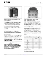
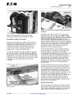
Figure 4-9 Shoot Bolt Handle Shown in Position “A” - Shoot
Bolts Retracted Fully Inside Cradle
Levering of the circuit breaker is discussed in
paragraph
4-6.4.
The three shoot bolt handle
positions (A, B and C) are shown Figures
4-7, 4-8
and
4-9).
Retract the shoot bolts by pushing the shoot bolt
handle down to Position “A” (Figure
4-9)
and push the
circuit breaker the rest of the way into the cassette
against the stop. At this point, the front of the cradle
will be flush with the front of the cassette. Rotate the
shoot bolt handle up to Position “B” (Figure
4-8)
permitting the shoot bolts to protrude partially into the
rectangular slots of the interlock plates on each side
of the cassette. The circuit breaker is now held in the
DISCONNECT position.
For the circuit breaker to be in the TEST position, the
secondary connection must be made between the
breaker and the cassette. Refer to paragraph
4-6.3
for
details on making secondary connections to the
cassette.
Once the secondary connection is made and the shoot
bolt handle is in Position “C” (fully engaged), the
circuit breaker can be levered from the TEST position
to the CONNECTED position. For the circuit breaker
to reach its CONNECTED position, it must be
manually levered to that position as described in
paragraph
4-6.4.
When the circuit breaker is levered
to the CONNECTED position, the lower cradle portion
remains locked in the position dictated by the shoot
bolts. The upper portion of the circuit breaker moves
into the structure to the CONNECTED position.
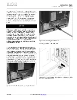
4-6.3 DRAWOUT ELECTRICAL INTERFACES
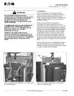
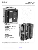
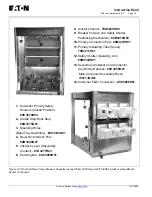
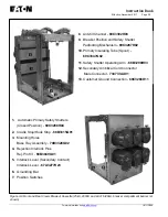
Circuit Breaker Secondary Connections
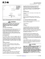
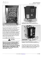
Secondary connections are made through the use of
an umbilical cord (Figure
4-10).
The secondary
connector on the breaker end of the cord is connected
to its compatible secondary connector located under a
protective hood on the upper front portion of the
circuit breaker (Figure
4-11). This connection is
already made when the breaker is shipped from
the factory.
If there is a need to make this connection
in the field, it can be simply accomplished as follows:
Connect the breaker side connector of the umbilical
cord to the circuit breaker’s connector. Once the
push-in connection is made, the breaker end of the
umbilical cord is secured in place with two self
threading screws that screw into two mounting holes
in the top of the breaker’s secondary mounting
hardware. With the breaker end of the umbilical cord
securely in place, take the cassette end of the
umbilical cord and carefully lay it over the front of the
circuit breaker in preparation for movement of the
breaker into the cassette (Figure
4-10).
At this point,
the circuit breaker is ready to be inserted into its
cassette. Refer to paragraph
4-6.2
for details on
positioning of the circuit breaker for insertion into its
cassette.
Summary of Contents for 50 VCP-TR16
Page 2: ......


