Instruction Book
Effective: November 2017
Page 31
IB131016EN
For more information visit:
www.Eaton.com
SECTION 5: DESCRIPTION AND OPERATION
5-1 INTRODUCTION
The VCP-T vacuum circuit breaker is a drawout device
while the VCP-TR circuit breaker is a fixed mounted
device. The VCP-T drawout circuit breaker is comprised of
two parts. The upper circuit breaker element, much like the
fixed VCP-TR circuit breaker element and a lower portion
called the cradle. The cradle primarily provides the
levering mechanism for moving the circuit breaker into and
out of the CONNECTED position. They are designed,
tested and in accordance with ANSI Standards C37.04,
C37.09 and C37.20.2. The ratings are shown in Table
1.1.
The circuit breakers utilize a proven two step stored energy
mechanism, which is available as standard with manually
charged closing springs or optionally with electrically
charged closing springs. A high degree of service
continuity is provided by the open-close open (O-CO)
circuit breaker duty cycle. A wide range of AC and DC
control voltages are available: 24, 48, 110, 125, 220 and
250 Vdc, and 110, 120, 220 and 240 Vac.
VCP-T and VCP-TR circuit breakers are true metal-clad
circuit breakers encompassing all the features normally
associated with a true metal-clad design, such as:
Insulation and isolation of compartments
11 gauge grounded steel safety barrier between
primary and mechanism compartments
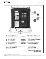
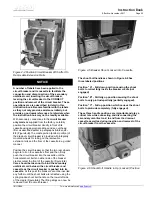
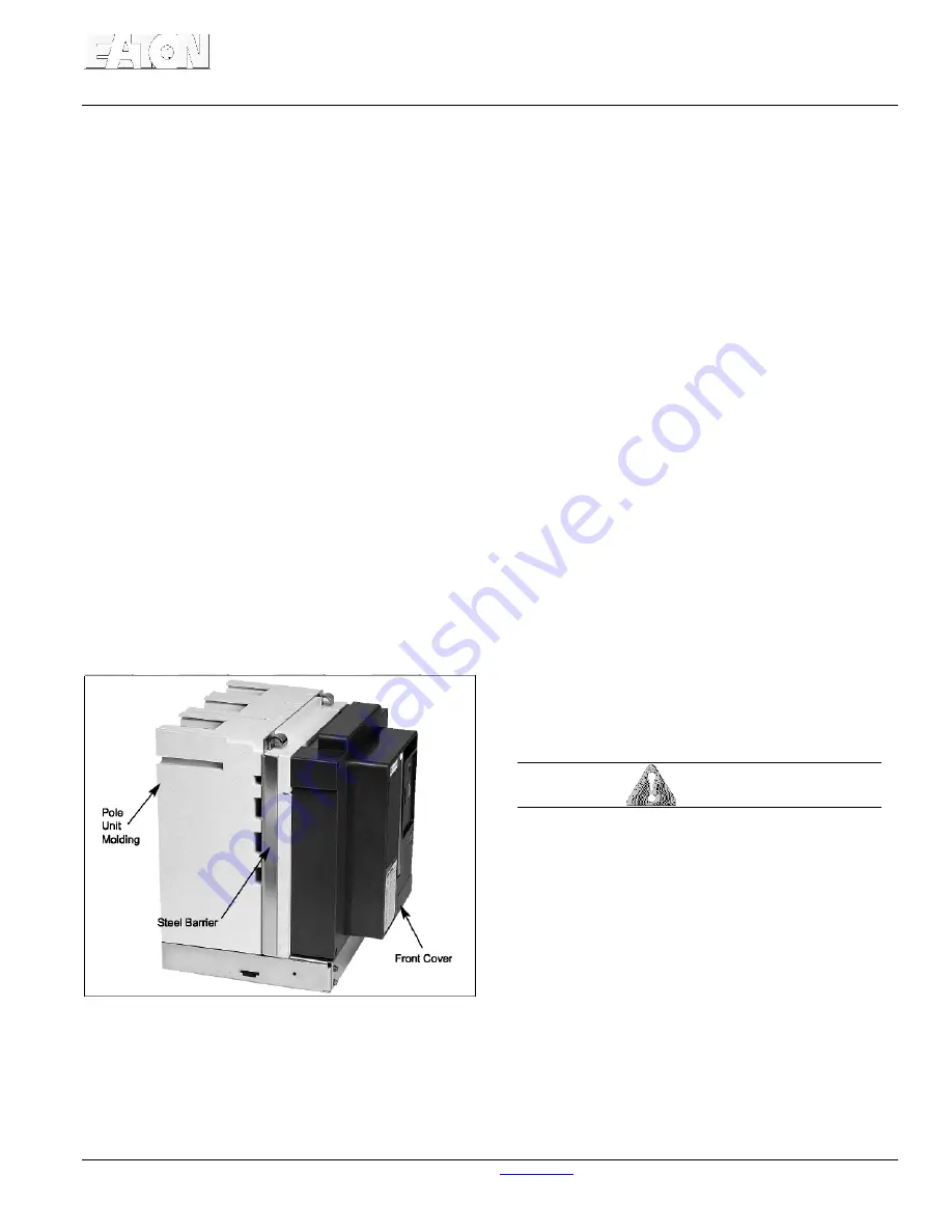
Figure 5-1 Typical Rigid Frame Construction
The circuit breakers utilize a rigid frame construction of
engineered thermoset composite resins with a patented
pole unit molding. In addition to high strength structural
properties, the material used has excellent dielectric
characteristics and resists tracking (Figure
5-1).
The
fixed type VCP-TR circuit breaker element uses copper
primary conductors with silver plated joints.
Upper and lower conductors have two holes for
making bolted horizontal bus or cable connections.
Secondary connections can be made through a
standard secondary disconnect block or an optional
screw type terminal block supplied in kit form.
The drawout VCP-T circuit breakers utilize spring
loaded finger disconnects to make its primary
connection. The number of individual silver plated
fingers that make up a finger cluster depends upon the
current rating of the circuit breaker. The circuit breaker
finger disconnects mate with rigidly mounted, silver
plated stabs mounted in the rear portion of the
cassette.
Controls and indicators, common to all ratings, are
functionally grouped on the front of the circuit breaker.
The front escutcheon (faceplate) is also common for all
voltage and current ratings. A mechanical operations
counter is provided as standard on all circuit breakers.
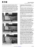
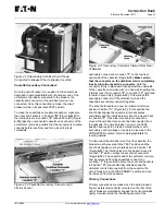
VCP-T drawout type and VCP-TR fixed type circuit
breakers are supplied as standard with a front
mounted 5a, 5b auxiliary switch for customer use. The
switch is a heavy duty, double break type switch with
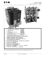
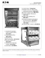
wipe type contacts (Figures
5-2
and
5-3).
5-2 VACUUM INTERRUPTER ASSEMBLY
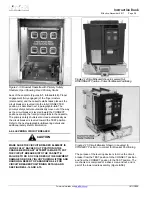
All VCP-T and VCP-TR circuit breakers utilize vacuum
interrupters for interruption and switching functions
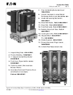
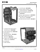
(Figures
5-4
and
5-5
and
5-5a).
Vacuum interruption
offers the advantages of enclosed interrupters,
reduced size and weight, short interrupting time, long
life, reduced maintenance, and environmental
compatibility.
WARNING
DO NOT PLACE ANY CIRCUIT BREAKER IN
SERVICE WITHOUT ITS SUPPLIED HORIZONTAL
AND VERTICAL BARRIERS, IF SO SUPPLIED,
BEING PROPERLY IN PLACE. FAILURE TO
COMPLY WITH THIS WARNING CAN CAUSE A
CATASTROPHIC FAILURE RESULTING IN DEATH,
SEVERE PERSONAL INJURY AND
PROPERTY/EQUIPMENT DAMAGE.
The vacuum interrupters are mounted vertically and
supported from the fixed stem connected to the top
conductor. A patented pole unit molding encloses each
of the vacuum interrupter assemblies on three sides up
to 25kA and four sides on 31.5 and 40kA breakers
providing the required mounting means, insulation,
isolation, strength and rigidity. Certain VCP-T and VCP-
TR circuit breakers are supplied with vertical and
horizontal barriers already in place and are required to
be in place before the circuit breaker is put
Summary of Contents for 50 VCP-TR16
Page 2: ......

