26
Instruction Book
IB182012EN March 2017 www.eaton.com
50DH-VR-50AXU / 50XU / 75U / 75ARU - 600 / 1200A
Replacement Circuit Breaker
5.3 INSERTION PROCEDURES
5.3.1 50-DH-VR-50 AXU/75U (FRONT RACKING)
a. Place the circuit breaker in the withdrawn position out of the cell.
The racking handle is not required for this position and the racking
system interlocks are not automatic outside the cell. The circuit
breaker can be mechanically operated in this position if the position
mode indicator reads “TEST/OPERATE”. Extreme care should be
exercised to avoid inadvertent operation and possible injury or
equipment damage.
WARNING
THE CIRCUIT BREAKER CAN BE OPERATED WHEN WITHDRAWN FROM
THE CELL AND EXTREME CARE SHOULD BE EXERCISED TO AVOID
INADVERTENT OPERATION AND POSSIBLE INJURY OR EQUIPMENT
DAMAGE.
b. From the withdrawn position, ensure the circuit breaker is open
and the mechanism is completely discharge. Engage the racking
handle and rotate the racking handle counter-clockwise as far as
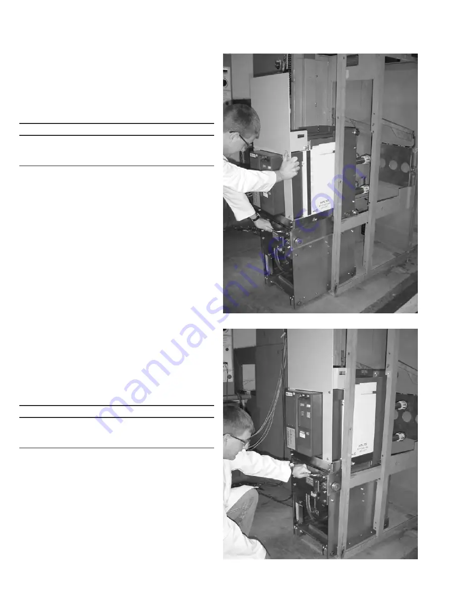
possible and align the circuit breaker wheel rails with the guide rails
of the cell. (See Figure 5.6)
c. Check that the closing spring status indicator reads
“DISCHARGED” and that the main contact status indicator reads
“OPEN”. Manually trip, close, an trip the circuit breaker as needed to
obtain this status.
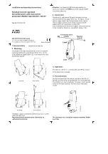
d. Push the circuit breaker into the cell until all the wheels are on
the cell floor and the circuit breaker halts as the racking arm rollers
meet the guide slots of the cell (Figure 5.7).
e. Engage the racking handle (Figure 3.1) and rotate the handle
clockwise a 1/2 turn until the “DISCONNECT” position is reached
and the circuit breaker will now be held captive in the compartment.
The circuit breaker can not be operated because of the racking
mechanism trip cam interface with the circuit breaker trip linkage.
f. To rack the circuit breaker further into the cell, rotate the
racking handle clockwise. In approximately 1 - 1/2 clockwise
turns of the racking handle, the position indicator (Figure Set 3.3)
will reflect “TEST/OPERATE”. In the “TEST” position, the circuit
breaker can be closed and tripped manually and electrically, thus
allowing maintenance test or checks. To operate the circuit breaker
electrically, the secondary disconnect must be engaged at this
time. Release the secondary disconnect slider by pulling the catch
pin and pushing the slider toward the rear several inches. The
slider is located on the lower left area of the circuit breaker frame.
Push on the front side flat surface of the slider until the secondary
disconnect can be felt to be fully engaged with the secondary
disconnect of the switchgear.
NOTICE
ONCE THE SECONDARY DISCONNECT BLOCK IS ENGAGED IN THE “TEST”
POSITION, IT WILL REMAIN CONNECTED THROUGHOUT FURTHER INWARD
MOVEMENT AS THE CIRCUIT BREAKER ADVANCES FROM THE “TEST” TO
THE “CONNECT” POSITION.
The spring charging motor will begin to run and charge the closing
spring as the secondary connection is made as long as control
power is available. The circuit breaker is now in the “TEST” position,
with control voltage applied and ready for electrical or manual
testing.
g. To advance from the “TEST” position, continue turning the
racking handle clockwise. The circuit breaker will travel approximately
nine (9) inches. Towards the end of travel, the racking torque will
increase due to the additional resistance of the primary disconnect
contact fingers engaging the cell copper. The circuit breaker will be
considered in the “CONNECT” position when the position indicator
reads “TEST/OPERATE”. This indicates that the trip linkage is
released and the circuit breaker is now ready for service.
Figure 5.6. Alignment of 50DH-VR (50XU/75ARU Shown)
Figure 5.7. Insertion of 50DH-VR (50XU/75ARU Shown)


