18
Instruction Book
IB02707112E
August 2015
50/75VCPW-VSR
Breaker To Vacuum Starter Replacement Unit
EATON CORPORATION www.eaton.com
procedures are similar. If it is necessary to reference anything in the
unit compartment, refer to the original instruction books supplied
with the assembly.
Refer to Figures 3.3 and 3.4, for any parts identification required
during these installation procedures.
a. The starters faceplate and barriers must be positioned properly
and securely bolted in position, as shown in Figures 3.3 and 3.4,
before inserting the starter into the cell.
b. Carefully follow the insertion procedure in section 5 to get
the VSR unit into the test position inside the compartment and
to engage the secondary contacts to proceed with the electrical
operations check.
WARNING
AS SOON AS THE SECONDARY CONTACTS MATE UP, THE STARTER IS
READY FOR OPERATION IF THE CONTROL CIRCUIT IS ENERGIZED.
c. Once the starter is in the test position, it may be electrically
closed and tripped by using a control switch on the cell door, or it
may be manually tripped by means of the trip button, located on the
faceplate of the starter.
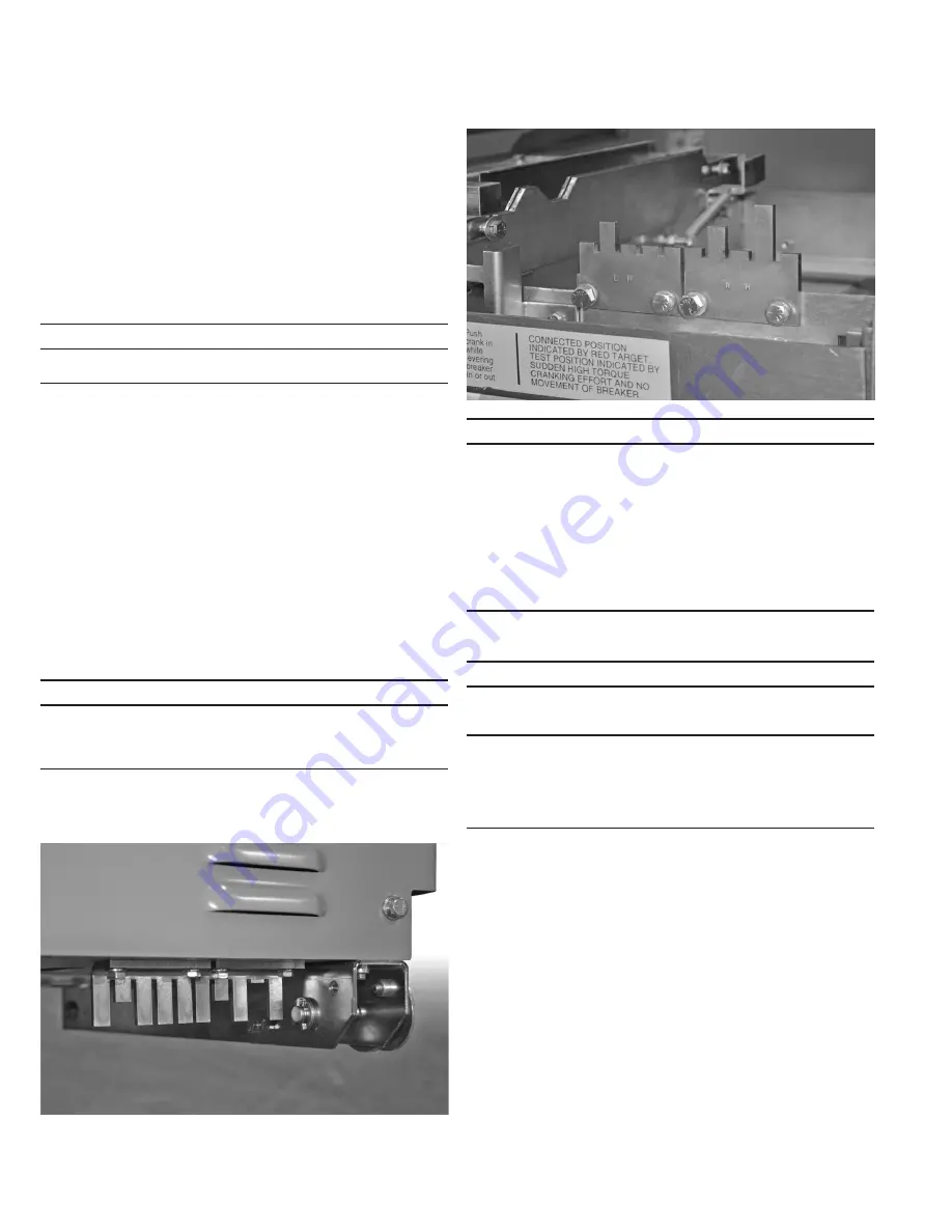
5.9 CELL CODE / REJECTION PLATE INSTALLATION
Cell code plates and circuit breaker rejection plates are required to
reject circuit breakers and breaker to vacuum starter replacement
units that do not match the electrical rating structure of the existing
cell. If the momentary rating of a unit is increased, a code plate and
a cell rejection plate must be installed to accept the new unit and
reject all others of lesser ratings. If momentary ratings of the new
unit is the same as the original breaker, then the original cell code
plate may be retained.
A unit code plate is factory installed on VSR-series units. Cell code
plates are automatically furnished with each unit. (Rejection plates
have stamped orientation as “LH” and “RH” for clarity.) (Figure 5.5)
NOTICE
REJECTION PLATES MUST BE INSTALLED INTO THE PROPER INTENDED
SWITCHGEAR PER THE NAMEPLATE RATING. IF THE REJECTION PLATE IS
NOT INSTALLED CORRECTLY THE VSR CAN NOT BE INSERTED INTO THE
INTENDED STRUCTURE.
WARNING
ARC FLASH INCIDENCES WITH MV SWITCHGEAR CAN OCCUR DURING THE
PROCESS OF INSERTING AND REMOVING VSR UNITS IN SWITCHGEAR
CUBICLES. IT IS STRONGLY RECOMMENDED THAT PROPER PPE
(PERSONAL PROTECTIVE EQUIPMENT) BE WORN BY PERSONNEL WHO
RACK UNITS USING THE MANUAL RACKING HANDLE OR THE ROTARY
RACKING HANDLE. EATON CORPORATION PROVIDES A UNIVERSAL
REMOTE POWER RACKING SYSTEM (RPR-2) WHICH IS COMPATIBLE WITH
THE INTERNAL ROTARY RACKING UNITS. THIS SYSTEM MAY ALLOW
PERSONNEL TO WEAR A LOWER LEVEL OF PPE DURING THE INSERTION
OR REMOVAL PROCESS AS LONG AS RACKING CAN BE PERFORMED FROM
OUTSIDE THE FLASH PROTECTION BOUNDARY.
5.10 INSERTION PROCEDURE
WARNING
EXAMINE THE INSIDE OF THE CELL BEFORE INSERTING THE STARTER
FOR EXCESSIVE DIRT OR ANYTHING THAT MIGHT INTERFERE WITH THE
STARTER TRAVEL.
KEEP HANDS OFF THE TOP EDGE OF THE FRONT BARRIER WHEN PUSHING
A STARTER INTO A CELL. FAILURE TO DO SO COULD RESULT IN BODILY
INJURY, IF FINGERS BECOME WEDGED BETWEEN THE STARTER AND
THE CELL. USE BOTH FULLY OPENED HANDS FLAT ON THE FRONT OF THE
STARTER TO ADVANCE INO THE STRUCTURE.
If the VCPW-VSR is being inserted into an upper compartment or
will be positioned in a lower compartment without the use of a
drawout ramp or dockable dolly, the extension rails must first be
put in position. Carefully engage the left and right extension rails to
the fixed structure rails and ensure they are properly seated in place
(Figure 5.6). Once the extension rails are properly in place, the VSR
can be carefully loaded on the extension rails using an overhead lifter
and lifting yoke. Remove the lifting yoke when the VSR is securely
seated on the extension rails.
Push the VSR into the compartment until the TEST position is
reached as confirmed by a metallic sound of the racking latch
engaging the racking nut (Figures 5.7). Once the VSR is in the TEST
position, the extension rails can be removed.
To engage the secondary contacts, raise the handle to the
secondary disconnect cage and pull the cage forward as far as
possible (Figure 5.8). As soon as control power is available, the
motor will start charging the closing springs.
Figurt 5.5. VCPW-VSR RtjtcoiNn Plaot (230A VSR ShNwn)
Figurt 5.4. VCPW-VSR CNdt Plaot (250MVA VSR ShNwn)


