31
Instruction Leaflet
IL01301051E
effective September 2013
Operating Manual for Series NRX
Trip Units - Digitrip™ 520/520M
EATON
www.eaton.com
Appendix D: Performance testing for ground
fault trip units—primary injection
North American Testing Requirements
In North America and certain other countries it is required that any
ground fault protection system be performance tested when first
installed. Conduct tests in accordance with the approved instructions
provided with the equipment. Make a written record of this test
and make the results available to the authority having inspection
jurisdiction.
Standards requirements
As a follow-up to the basic performance requirements stipulated
by the NEC, UL Standard No. 1053 requires that certain minimum
instructions must accompany each ground fault protection system.
These statements (in General Test Instructions), plus a copy of the
record forms (
Figure 28, Figure 29, and Figure 30
), are included as
part of this instructional leaflet.
General test instructions
The interconnected system must be evaluated only by qualified
personnel and in accordance with the equipment assembler’s detailed
instructions.
To avoid improper operations following apparently correct simulated
test operations, the polarity of the neutral sensor connections (if used)
must agree with the equipment assembler’s detailed instructions.
Where a question exists, consult the specifying engineer and/or
equipment assembler.
•
WARNING
ELECTRICAL SHOCK OR BURN INJURY CAN OCCUR WHEN WORKING ON
POWER SYSTEMS. ALWAYS TURN OFF POWER SUPPLYING CIRCUIT BREAKER
BEFORE CONDUCTING TESTS. TEST OUT OF THE CELL, IF POSSIBLE.
Verify the grounding points of the system using high voltage testers
and resistance bridges to ensure that ground paths do not exist that
could bypass the sensors.
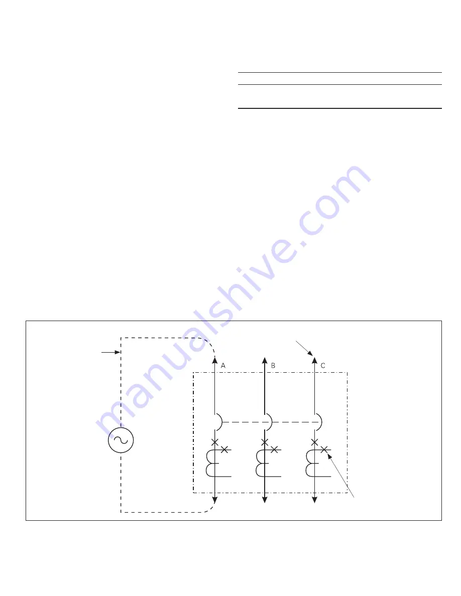
Use a low voltage (0- to 24-volt), high-current, AC source to apply a
test current of 125 percent of the ground pickup setting through one
phase of the circuit breaker. This should cause the circuit breaker to
trip in less than 1 second and operate the alarm indicator, if one is
supplied. Reset the circuit breaker and the alarm indicator. Repeat the
test on the other two phases (
Figure 26
).
Apply the same current as described above through one phase of
the circuit breaker, returning through the neutral sensor. The breaker
should not trip, and the alarm indicator, if one is supplied, should not
operate. Repeat the test on the other two phases.
Apply the same current as described above through any two phases of
the circuit breaker. The breaker should not trip, and the alarm indicator,
if one is supplied, should not operate. Repeat the test using the other
two combinations of circuit breaker phases (
Figure 27
) or through a
breaker pole and the neutral that employs a neutral sensor. Record the
test results on the test form provided with the equipment (
Figure 30
).
Figure 26.
Suitable
Connectors
Low Voltage AC
Current Source
Primary Disconnect
Stabs (drawout only)
Polarity and
Identification
CNnnecoiNn Deoails fNr CNnducoing Single-PNle, Single-Phase Curreno Tesos Wioh ohe Circuio Breaker RemNved FrNm ohe Cell


