background image

Page 18

614-03898-00_EN

3. Installation

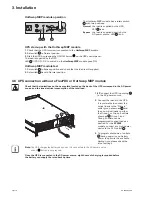
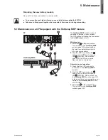
HotSwap MBP module operation

UPS ON

OK 

to

 switch

Nor

ma

l

UPS OUT

ByP

as

s

29 30

31

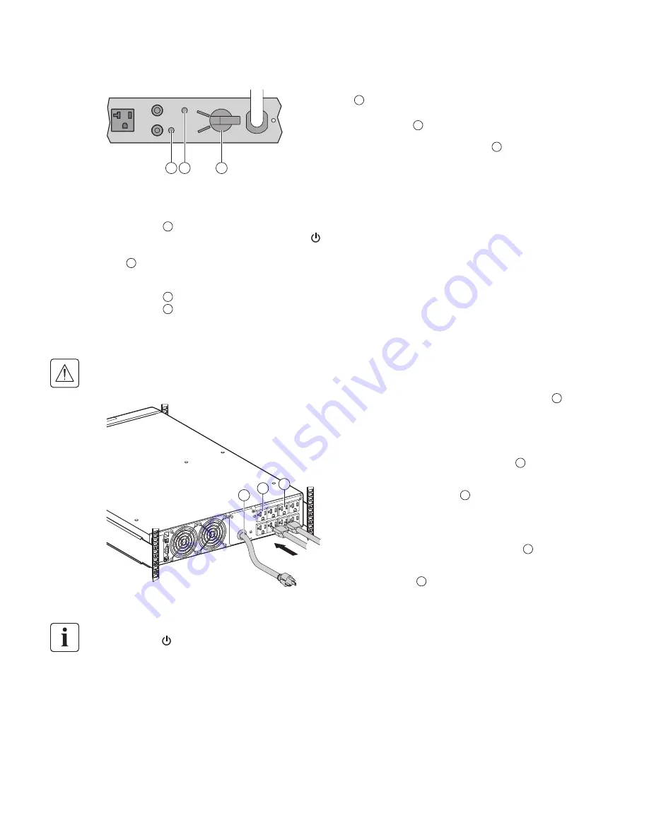
UPS start-up with the HotSwap MBP module

1.

 Check that the UPS is correctly connected to the 

HotSwap MBP

 module.

2.

 Set switch 

31

 to Normal position.

3.

 Start the UPS by pressing the ON/OFF button   on the UPS control panel. 

The load is supplied by the UPS.
LED 

29

 "UPS ON - OK to switch" on the 

HotSwap MBP

 module goes ON.

HotSwap MBP module test

1.

 Set switch 

31

 to Bypass position and check that the load is still supplied.

2.

 Set switch 

31

 back to Normal position.

The HotSwap MBP module has a rotary switch 

31

 with two positions:

Normal

   the load is supplied by the UPS,  

LED 

29

 is on.

Bypass

   the load is supplied directly by the 

AC-power source. LED 

30

 is on.

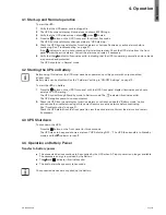
3.8  UPS connection without a FlexPDU or HotSwap MBP module

Check that the indications on the name plate located on the back of the UPS correspond to the AC-power 
source and the true electrical consumption of the total load.

10

9

8

1.


5P

: connect the UPS input plug 

10


to the AC-power source.

2.

  Connect the loads to the UPS.   

It is preferable to connect the  

critical loads to the ‘Primary’  

outlet group shown as 

9

 and  

the non-critical loads to either  

the Group 1 or Group 2 outlets 

shown as 

8

. Group 1 and  

Group 2 outlets can be  

programmed to shed loads as 

desired. For the 

5P 3000 


models, connect any high-power 

device to the 30 A outlet 

7

.

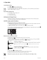
3.  

To program shutdown of outlets 

8

 during operation on battery 

power to optimize the available 

backup time, please check the  

in/out settings.

Note:

  The UPS charges the battery as soon as it is connected to the AC-power source,  

even if 


button

 is not pressed.

Once the UPS is connected to the AC-power source, eight hours of charging is required before  
the battery can supply the rated backup time.

Summary of Contents for 5P 1500 RT

Page 1: ...ENGLISH 5P 1500 RT 5P 2200 RT 5P 2200 5P 3000 RT 5P 3000 Installation and user manual Copyright 2012 EATON All rights reserved Service and support Call your local service representative 614 03898 00_EN ...

Page 2: ...Page 2 614 03898 00_EN ...

Page 3: ... installation and maintenance of the UPS and batteries The 5P models that are covered in this manual are intended for installation in an environment within 0 to 40 C free of conductive contaminant This equipment has been tested and found to comply with the limits for a Class A digital device pursuant to Part 15 of the FCC Rules These limits are designed to provide reasonable protection against har...

Page 4: ...roduct Safety The UPS connection instructions and operation described in the manual must be followed in p p the indicated order A protection circuit breaker must be installed upstream and be easily accessible p p The system can be disconnected from the AC power source by opening this circuit breaker Check that the indications on the rating plate correspond to your AC powered system and to p p the ...

Page 5: ...orts 16 3 6 Connection with a FlexPDU Power Distribution Unit module optional 17 3 7 Connection with a HotSwap MBP module optional 17 3 8 UPS connection without a FlexPDU or HotSwap MBP module 18 4 Operation 19 4 1 Start up and Normal operation 19 4 2 Starting the UPS on Battery 19 4 3 UPS Shutdown 19 4 4 Operation on Battery Power 19 4 5 Return of AC Input Power 20 4 6 UPS remote control function...

Page 6: ...er 50 of recycled cardboard p p Sacks and bags are made of polyethylene p p Packing materials are recyclable and bear the appropriate identification symbol p p 01 PET Materials Abbreviations Number in the symbols Polyethylene terephthalat PET 01 High density polyethylene HDPE 02 Polyvinyl chloride PVC 03 Low density polyethylene LDPE 04 Polypropylene PP 05 Polystyrene PS 06 Follow all local regula...

Page 7: ...tions Tower installation D W H Rack installation D H W Description Weights lb kg Dimensions inch mm D x W x H 5P 1500 RT 58 60 26 60 20 6 x 17 4 x 3 4 522 x 441 2 x 86 2 5P 2200 RT 60 20 27 30 5P 2200 5P 3000 RT 81 10 36 80 25 5 x 17 4 x 3 4 647 x 441 2 x 86 2 5P 3000 ...

Page 8: ...d 5 Connector for ROO remote ON OFF or RPO Remote Power OFF control 7 30A outlet L5 30R for connection of equipment for 5P 3000 only 8a Group 1 2 programmable outlets for connection of equipment 8b Group 2 2 programmable outlets for connection of equipment 9 Primary Group outlets for connection of critical equipment 10 Attached 8 ft input power cord for AC power source 5 15P for 1000 1500 5 20P fo...

Page 9: ...cator green On battery Indicator yellow Alarm Indicator red Normal mode 100 17min 100 2 7kW 3kVA Efficiency 98 Escape Up Down Enter On Off button The following table shows the indicator status and description Indicator Status Description Green On The UPS is operating normally Yellow On The UPS is on battery mode Red On The UPS has an active alarm or fault See trouble shooting on page 21 for additi...

Page 10: ... button is pressed Normal mode The UPS is operating normally The UPS is powering and protecting the equipment In AVR mode No beep The UPS is operating normally but the utility voltage is outside normal mode thresholds The UPS is powering the equipment through a Automatic Voltage Regulation device The equipment is still normally protected On Battery Battery LED is on 1 beep every 10 seconds A utili...

Page 11: ... 6 User settings The following table displays the options that can be changed by the user Description Available settings Default settings Local settings Language English French German Italian Portuguese Spanish Russian Menus status notices and alarms UPS fault Event Log data and settings are in all supported lan guages English User selectable when UPS is powered for the first time LCD settings Aut...

Page 12: ...o restart automatically when mains recovers after a complete battery discharge Enable Energy saving Disable Enable If Enable UPS will shutdown after 5 min of back up time if no load is detected on the output Disable Sleep mode Disable Enable If disable LCD and communication will turn OFF immediately after UPS is OFF If enable LCD and communication stays ON 1h30 min after UPS is OFF Disable Remote ...

Page 13: ...mmunication cable 18 Software CD ROM 19 Manual CD ROM 20 Safety instructions 21 Quick start 22 Mounting kit for 19 inch bays RT only 23 2 supports for the upright position 24 NMC communication card optional Packing materials must be disposed of in compliance with all local regulations concerning waste Recycling symbols are printed on the packing materials to facilitate sorting ...

Page 14: ... battery Note A small amount of arcing may occur when connecting the batteries This is normal and does not damage the UPS or present any safety concern A C B A Connect the battery module never pull on the wires B Attach the left hand side of the front panel by sliding it then by locking the push button C Attach the center panel ...

Page 15: ...14 03898 00_EN ENGLISH 3 Installation 3 3Tower installation 3 4 Rack installation RT only Follow steps 1 to 4 for module mounting on the rails 1 1 3 4 4 3 2 The rails and necessary hardware are supplied by EATON ...

Page 16: ...tion cards optional standard on the Netpack versions It is not necessary to shutdown the UPS before installing a communication card 1 Remove the slot cover 4 secured by screws 2 Insert the communication card in the slot 3 Secure the card cover with the 2 screws Characteristics of the contact communication port optional Pins 1 3 4 5 6 10 not used p p Pin 2 common user p p Pin 7 low battery p p Pin ...

Page 17: ...replace the UPS without affecting the connected loads HotSwap function UPS ON OK to switch Normal UPS OUT UPS IN AC POWER ByPass HotSwap MBP 5P 28 29 30 31 34 32 33 1 Connect the input socket 34 on the HotSwap MBP module to the AC power source 2 Connect the UPS input socket 10 to the UPS Input 33 of the HotSwap MBP module This cord and the receptacle are marked blue 3 Connect the UPS outlet 7 to t...

Page 18: ... FlexPDU or HotSwap MBP module Check that the indications on the name plate located on the back of the UPS correspond to the AC power source and the true electrical consumption of the total load 10 9 8 1 5P connect the UPS input plug 10 to the AC power source 2 Connect the loads to the UPS It is preferable to connect the critical loads to the Primary outlet group shown as 9 and the non critical lo...

Page 19: ...abled See the Cold start setting in ON OFF Settings on page 12 To start the UPS on battery 1 Press the button on the UPS front panel until the UPS front panel display illuminates and shows a status of UPS starting The UPS cycles through Standby mode to Battery mode The indicator illuminates solid The UPS supplies power to your equipment 2 Check the UPS front panel display for active alarms or noti...

Page 20: ...ton to shut down the UPS These functions are obtained by opening a contact connected between the appropriate pins of connector 5 on the rear panel of the UPS see figures below 5 Remote control connection and test 1 Check that the UPS is OFF and disconnected from the AC input source 2 Remove connector 5 3 Connect a normally closed volt free contact 60 V DC 30 V AC max 20 mA max 0 75 mm2 18 AWG cabl...

Page 21: ...tect the equipment anymore Note The alarm message and the UPS Serial Number then contact your service representative Troubleshooting a UPS equipped with the HotSwap MBP module Indication Diagnostic Correction 1 The load is no longer supplied when the rotary switch 33 on the HotSwap MBP module is set to Bypass position l The protected devices are connected to the UPS output instead of to the HotSwa...

Page 22: ...and all other metal objects from the hands and arms p p use tools with an insulated handle p p Battery module removal E D C A B A Remove the middle panel B Remove the left hand side of the front panel by pushing the button and then by sliding the part C Disconnect the battery module by separating the town connectors never pull on the wires D Remove the metal protection cover in front of the batter...

Page 23: ...e red LED on the HotSwap MBP module goes ON indicating that the load is supplied directly with AC input source power 2 Stop the UPS by pressing the button on the UPS control panel LED 29 UPS ON OK to switch goes OFF the UPS can now be disconnected and replaced Return to normal operation 1 Check that the UPS is correctly connected to the HotSwap MBP module 2 Start the UPS by pressing the button on ...

Page 24: ... Operating temperature range l Storage temperature range l Relative humidity l Noise level 0 to 40 C 15 to 50 C 20 to 90 without condensation 45 dBA 50 dBA 1 The high and low thresholds can be adjusted using UPS settings 2 Up to 40 Hz in low sensitivity mode programmable using UPS settings 3 Adjustable to 100 V For Models 5P 3000 5P 3000 RT CAUTION To reduce the risk of fire connect only to a circ...

Page 25: ... Module with UPS outlets for installation in a bay There are different modules with dif ferent types of outlets HotSwap MBP UPS manual bypass module for maintenance There are different modules with different types of outlets Load Devices or equipment connected to the UPS output Low battery warning This is a battery voltage level indicating that battery power is low and that the user must take acti...

Reviews: