background image

Page 11


5P 750VA-1. 5 KVA US_EN


ENG

LI

S

H


Submenu


Available settings


Default settings


On/Off settings


Cold st art


[Disable] [Enable] 
Enables the product to be started 
on battery power. 
First cold start always disabled. 

Enable


Forced reboot


[Disable] [Enable] 
If mains recover during a shutdown 
sequence: 
- if enabled, shutdown sequence will 
complete and wait 10 seconds prior 
to restart 
- if disabled, shutdown sequence will 
not complete and restart will occur 
immediately.


Enable


Aut o rest art


[ Disable]  [ Enable]  
Enables t he product  t o rest art  
aut omat ically when mains recovers 
af t er a complet e bat t ery discharge.


Enable


Energy saving


[ Disable]  [ Enable]  
If  enabled,  UPS will shut  down af t er 
5min of  back-up t ime,  if  no load is 
det ect ed on t he out put .


Disable


Sleep mode


[ Disable]  [ Enable]  
If  disabled,  LCD and communicat ion 
will t urn OFF immediat ely af t er 
UPS is OFF.  
If  enabled,  LCD and communicat ion 
st ays ON 1h30 min af t er UPS is OFF.


Disable


Remot e command


[ Disable]  [ Enable] 
If  enabled,  shut down or rest art  commands 
f rom sof t ware are aut horised. 

Enable


RPO delay


[0 s] [1s ] [2 s]...[180 s] 

Delays remote power off command


[0 s]


Battery settings


Aut omat ic bat t ery 
t est  

[ No t est ]  [ Every day]  [ Every week]  
[ Every mont h]  
Available only if  bat t ery charge 
mode is set  t o const ant  charge.  

 
Every week(in constant charge,
otherwise following ABM 
battery test method) 

Low bat t ery warning  [ 1 %]  [ 2 %]  . . .  [ 100 %]  

The alarm t riggers when t he set  
percent age of  bat t ery capacit y is 
reached during a back-up t ime.  

20 % 

Rest art  bat t ery 
level 

[ 1 %]  [ 2 %]  . . .  [ 100 %]  
If  set ,  aut omat ic rest art  will occur 
only when percent age of  bat t ery 
charge is reached.  

0% 

Bat t ery charge mode  [ ABM cycling]  [ Const ant  charge]  

ABM cycling 

Ext ernal bat t ery 

[ Aut o det ect ion]  [ Manual EBM set . ]  
[ Manual bat t ery set . ]  

[Auto detection] 
Using standard EBM, UPS 
detects automatically the 
number of EBM connected 

Deep discharge 
prot ect ion 

[ Yes]  [ No]  
If  set  t o Yes,  t he UPS aut omat ically 
prevent s bat t ery f rom deep 
discharge by adapt ing end of  
back-up t ime volt age t hreshold.  

Yes 


Summary of Contents for 5P750RC

Page 1: ...Page 1 ENGISH Copyright 2015 EATON All right s reserved 5P 750VA 1 5 KVA EU_EN Installation and user manual 5P750RC 5P1000RC 5P1500RC...

Page 2: ...l CISPR 22 EN 55022 Harmonics emission IEC 61000 3 2 Flickers emission IEC 61000 3 3 FCC 47 CFR Part 15 Subpart B Unint ent ional Radiat ors Class B Special symbols The following are examples of symbo...

Page 3: ...nd be easily accessible The syst em can be disconnect ed from t he AC power source by unplugging t he input cable Check t hat t he indicat ions on t he rat ing plat e correspond t o your AC powered sy...

Page 4: ...Battery module connection 13 3 3 Rack installation 14 3 4 Wall mounting of rack model 15 3 5 Communication ports 16 4 Operation 17 4 1 Start up and Normal operation 17 4 2 Starting the UPS on Battery...

Page 5: ...prises over 50 of recycled cardboard Sacks and bags are made of polyet hylene Packing mat erials are recyclable and bear t he appropriat e ident ificat ion symbol 01 PET Materials Abbreviations Number...

Page 6: ...tion 2 1 Standard installations Rack model Description Weights kg lb Dimensions mm inch D xW x H 5P750RC 14 1 31 1 370 440 86 2 14 6 17 3 3 4 5P1000RC 15 0 33 1 370 440 86 2 14 6 17 3 3 4 5P1500RC 18...

Page 7: ...t ional communicat ion card 3 Primary group Out let s for connect ion of crit ical equipment 4 Group 1 programmable out let s for connect ion of equipment 5 Group 2 programmable out let s for connect...

Page 8: ...oad status events measurements and settings 100 19min 1EBM The following t able shows t he indicat or st at us and descript ion Indicator Status Description Green On The UPS is operat ing normally Ora...

Page 9: ...he UPS is powering and protect ing t he equipment In AVR mode 1 beep every 10 seconds The UPS is operat ing normally but t he ut ilit y volt age is out side normal mode t hresholds The UPS is powering...

Page 10: ...he following t able displays t he opt ions t hat can be changed by t he user Submenu Available settings Default settings Local settings Language English Fran ais Deutsch Espa ol Portugu s Italiano Sim...

Page 11: ...ation stays ON 1h30 min after UPS is OFF Disable Remote command Disable Enable If enabled shutdown or restart commands from software are authorised Enable RPO delay 0 s 1s 2 s 180 s Delays remote powe...

Page 12: ...mounting kits 11 Quick start safety instructions and environmental document 12 RS232 communication cable 13 USB communication cable Packing materials must be disposed of in compliance with all local r...

Page 13: ...please connect the internal battery A Remove the center panel B Remove the left hand side of the front panel C Connect the battery module never pull on the wires D Attach the left hand side of the fr...

Page 14: ...N 3 3 Rack installation Follow steps 14 to 16 for model mounting on the rails Use provided screws on step 15 of installation Using a longer screw could present a safety risk The rails and necessary ha...

Page 15: ...Page 15 5P 750VA 1 5 KVA US_EN 3 4 Wall mounting of rack model Use provided screws on step 17 of installation Using a longer screw could present a safety risk...

Page 16: ...r 1 It is not necessary t o shut down t he UPS before inst alling a communicat ion card 1 Remove the slot cover 2 secured by screws 2 Insert the communication card in the slot 3 Secure the card cover...

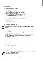
Page 17: ...See the Cold start setting in ON OFF Settings in section 2 6 To start the UPS on battery 1 Press the button on the UPS front panel until the UPS front panel display illuminates and shows a status of U...

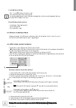
Page 18: ...These functions are obtained by opening a contact connected between the appropriate pins of connector 8 on the rear panel of the UPS see figures below Remote control connection and test 1 Check that t...

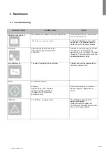
Page 19: ...Remove some of the equipment from the UPS The UPS continues to operate but may shutdown if the load increases The alarm resets when the condition becomes inactive End of battery life The end of the ba...

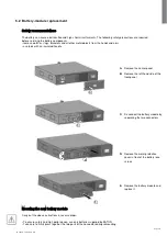
Page 20: ...ls with an insulated handle Mounting the new battery module Carry out the above instructions in reverse order To ensure safety and high performance use only batteries supplied by EATON Take care to fi...

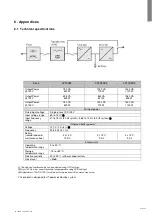
Page 21: ...stem 56 5 to 70 Hz 60 Hz system 2 Output on battery power Voltage 120 V 10 6 3 Frequency 50 60 Hz 0 1 Hz Battery sealed lead acid maintenance free 2 x 12 V 7 2 Ah 2 x 12 V 9 Ah 3 x 12 V 9 Ah Environme...

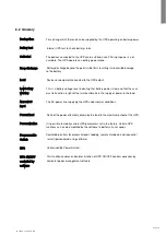
Page 22: ...low and that the user warning must take action in light of the imminent break in the supply of power to the load Normal AC The AC power line supplying the UPS under normal conditions input Percent lo...

Page 23: ...Page 23 5P 750VA 1 5 KVA US_EN www eaton com Powerquality Eaton 5P...

Reviews: