600 A 15/25 kV Class T-OP II connector assembly installation instructions
4
INSTALLATION INSTRUCTIONS
MN650048EN May 2017
●
●
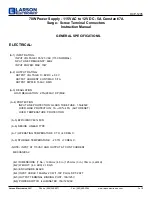
Remove alignment segment by applying pressure to the
T-Wrench to separate the alignment segment from the
LRTP. Recycle the align ment segment.
●
●
See Figure 9 for illustration of completed
LRTP installation.
LRTP
T-OP II ASSEMBLY
T-WRENCH
SEPARATED
ALIGNMENT
SEGMENT
Figure 9 . LRTP permanently installed into T-body
forming the T-OP II assembly
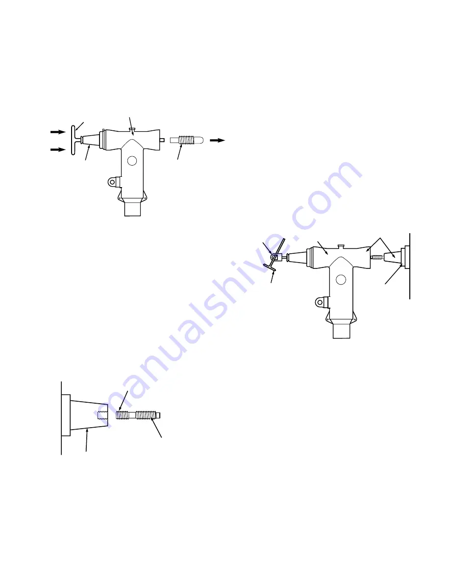
Install T-OP II assembly onto apparatus bushing
Step 8
Install stud into apparatus bushing
●
●
Ensure unit is de-energized.
●
●
Thread the shorter threaded end of the T-OP II stud
into the apparatus bushing until hand tight. (Refer to
Figure 10).
●
●
Engage the flats on the stud with a 1/2” wrench and
thread the stud into the bushing an additional 1/4
revolution past hand tight.
●
●
Remove any shavings that may have been raised during
the threading procedure.
APPARATUS BUSHING
SHORT THREADS
INTO BUSHING
EXTENDED
STUD (STUD-T)
Figure 10 . Line illustration of bushing stud installation
Step 9
Install the T-OP II assembly on the apparatus bushing
●
●
Clean and lubricate mating interfaces of the apparatus
bushing and T-body with the lubricant supplied.
●
●
Push the T-OP II assembly onto the apparatus bushing
until the extended length stud makes contact with the
rotating nut in the LRTP.
●
●
Insert the 5/16” torque tool into the 200 A tap and
engage the rotating nut. (Refer to Figure 11.)
●
●
Place a screwdriver or the T-wrench through the hotstick
operating eye of the torque tool (live-line tools can be
used to operate the T-OP II when de-energized) and
tighten the T-OP II assembly until the tool ratchets.
(20-25 ft.-lbs.)
ote:
N
If 5/16” hex rod (HD625) is used with customer
supplied torque wrench, thighten to 20-25 ft.-lbs.
●
●
Remove torque tool.
600 A
INTERFACES
APPARATUS
BUSHING
TQHD625
TORQUE TOOL
T-WRENCH
T-OP II
ASSEMBLY
Figure 11 . Installing the T-OP II assembly onto the
apparatus bushing
Step 10
Cap the 200 a interface
●
●
Clean and lubricate 200 A interface of LRTP and mating
apparatus (i.e., protective cap, grounding elbow, M.O.V.E.
arrester) with lubricant supplied. (Refer to Figure 12.)
●
●
To cap interface, follow installation instructions supplied
with the separable insulated connector used.