


16
Model 70360
13 When the needle bearing
assembly is replaced, the
numbered end of the bearing must
face toward the flange side of the
adapter to the dimension as
shown. (See Figure 13)
14 With the charge pump adapter
removed, remove the charge pump
assemblies outer and inner gerotor
ring. Next, remove the small drive
key from the pump shaft. (See
Figure 14 and 15)
15 Charge pumps are available in
two different displacements Charge
pump displacements are based on
the thickness of the gerotor
assembly and the depth of the pocket located in the charge
pump adapter. To determine the displacement, refer to the
table below.
Gerotor Pocket Depth
Displacement
Depth of Pocket
cm
3
/r [in
3
/r]
mm [in.]
6.9 [.42]
6.35 [.25]
13.8 [.84]
12.7 [.50]
16 To separate the backplate
assembly from the dowel pins in
the pump housing assembly, insert
two screwdrivers between
backplate and housing assembly
and pry upward. (See Figure 16)
17 After separation, remove the
backplate from the housing
assembly.
18 Turn the backplate assembly
over and inspect the needle
bearing. The needles in the needle
bearing must remain intact in the
bearing cage. (See Figure 17)
19 When the needle bearing
assembly is replaced, the
numbered end of the bearing must
face the valve plate side of the
backplate to the dimension as
shown. (See Figure 18)
20 With the backplate removed,
remove the gasket from the pump
housing assembly and discard.
(See Figure 19)
21 Remove the valve plate from the piston block assembly.
Note: This valve plate may have stuck to the backplate
assembly that was just previously removed.
22 Valveplate directional rotation (CW or CCW) is identified
by the location of the metering slots located on the face of the
valve plates. Pump input
rotation should always turn
into the metering slots.
(See Figure 20) A clockwise
valve plate is shown on the
left and a counter clockwise
valveplate is on the right.
Note: Whenever pump input rotation is changed, the valve
plate must be replaced along with the desired rotation charge
pump adapter.
23 Remove the rotating kit assembly by carefully retaining it
in the housing assembly. Lift the housing and rotating kit
assembly and turn over assemblies allowing the rotating kit
assembly to slide down the input shaft and out of the pump
housing.
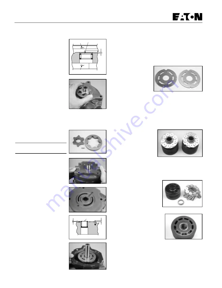
24 The model 70360 variable
displacement pumps are
available in two different
displacements. The 40,6 cm
8
/r
~ [2.48 in
3
/r] rotating kit
assembly is shown below on
the left. The 49,2 cm
3
/r [3.00 in
3
/r] rotating kit assembly is
shown below on the right. The 49,2 cm
3
lr [3 00 in
3
/r] rotating
assembly is easily identified by having larger pistons and
cutouts in the spider. (See Figure 21)
25 With the rotating kit
assembly removed, remove the
piston assemblies, spider and
spider pivot from the piston
barrel. (See Figure 22)
26 Inspect the piston
assemblies, spider, spider pivot
and piston block. The piston block
assembly usually requires no
further disassembly unless the pins
or block spring are damaged.
27 When any excessive wear or
scratches are noted on the face of
the piston block, the block
assembly must be replaced. (See Figure 23)
DO NOT LAP THE FACE OF PISTON BLOCK ASSEMBLY.
Numbered End
Gerotor Pocket
2.41 mm
[.095 in.]
Flange
Figure 13
Figure 14
Figure 15
Figure 16
Figure 17
2.79 mm
[.110 in.]
1.91 mm
[.075 in.]
Numbered End
Figure 18
Figure 19
Figure 20
Figure 21
Figure 22
Figure 23
Repair Information


