17
Model 70360
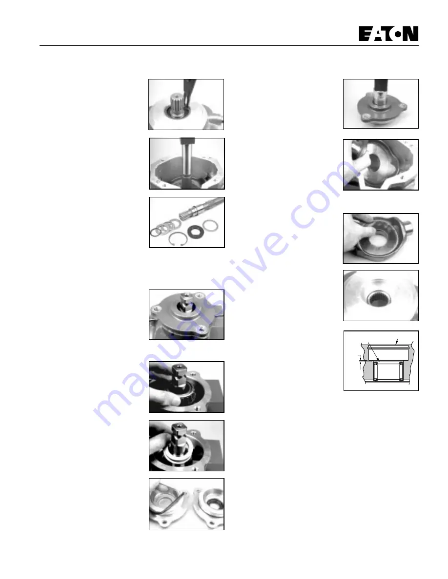
28 To remove the input shaft
assembly, use a pair of internal
snap ring pliers and remove the
shaft seal retaining ring from the
housing assembly. (See Figure 24)
29 With the retaining ring
removed, use a small press to
press the shaft seal and input shaft
assembly from the housing
assembly. (See Figure 25)
30 With the input shaft assembly
removed, disassemble the
assembly for inspection by
removing the shaft seal, washer,
retaining ring thrust washers and
bearing. (See Figure 26)
Note: The rear pump on tandem
units uses a spacer in place of shaft
seals.
31 To remove the camplate from the housing assembly, use a
9/16 in. socket or end wrench and remove the three cap
screws retaining the trunnion
coverplate assembly. Start at the
cover plate with trunnion controller
first. (See Figure 27)
32 With the retaining cap screws
removed, insert two small
screwdrivers in the notches located
in the cover plate assembly and pry upward.
33 Remove the tapered roller
bearing from the cam plate. (See
Figure 28)
Note: In most cases this tapered
roller bearing is a slip-fit on the
camplate.
34 With the tapered bearing
removed, remove the shims from
the camplate. (See Figure 29) Use
caution not to misplace or lose
these shims. Note: These shims
may vary in thickness and are used
to adjust camplate end play.
35 Reposition the pump assembly
to remove opposite cover plate.
Repeat steps 31 through 33.
36 Use an o-ring pick or similar
tool remove the o-ring seals from
the two cover plates. (See Figure 30)
37 To remove the control side
cover plate lip seal, use a small
press and press the lip seal inward.
(See Figure 31)
38 With the camplate bearings
removed, slide the camplate toward
the control side and lift it from the
pump housing. (See Figure 32)
Note: The camplate control shaft
will fit out either side of the pump
housing. Be sure to note on which
side of the housing the control
shaft protrudes before removing
camplate from housing for correct
reassembly orientation.
39 Remove the thrust plate from
the camplate. The thrust plate is
reversible and either side may face
the camplate. (See Figure 33)
40 Inspect the housing
assemblies front needle bearing. If
the needles remain in their cage
and move freely, replacement
usually is not required. (See Figure
34)
41 When the needle bearing is
replaced, the numbered end of the
needle bearing must face away
from the housing and pressed to
the dimension as shown. (See
Figure 35)
Figure 24
Figure 25
Figure 26
Figure 27
Figure 28
Figure 29
Figure 30
Repair Information
Figure 31
Figure 32
Figure 33
Figure 34
1.78 mm
[.07 in.]
Numbered End
Flange End of Housing
Figure 35