background image

18

Model 70360

Reassembly

1

Before reassembling the pump, replace all worn and

damaged parts, assemblies, seals and o-rings. Lubricate the
seals and o-rings with petroleum jelly to help retain them
during reassembly and to provide lubrication to the input and
control shaft seals. Lubricate all finished part surfaces freely
with clean hydraulic fluid to help
provide start up lubrication
between all rotating parts.
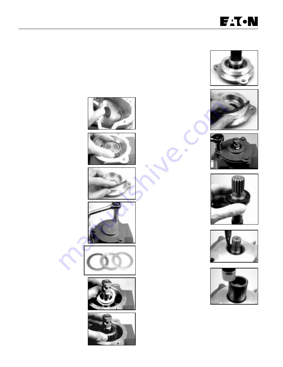
2

To reassemble the camplate

into the pump housing, tilt the
camplate slightly and install the
control side of the camplate
through the previously noted or
marked side of the housing
assembly. (See Figure 36)

3

With the camplate installed,

lubricate and install the tapered
bearing on the non-control arm
side of the camplate. (See Figure
37)

4

Lubricate and install the o-ring

seal on trunnion cover. (See Figure
38)

5

Install the trunnion cover over

bearing and on pump housing.
Install the three cap screws and
torque to 40,7 Nm [30 ft. lbs.].
(See Figure 39)

6

Shims are used to adjust the

camplate’s tapered bearings
preload. The shims used may be
thick, thin or both. When
repairing, start with the same
thickness of shims as those
removed then add or delete to
obtain the proper bearing
preload. (See Figure40)

7

Install the shims on the control

arm side of the camplate. (See
Figure 41)

8

With the shims installed,

lubricate and install the tapered
bearing on the control arm side of
the camplate. (See Figure 42)

9

Lubricate and install the

control arm shaft seal into the
control arm trunnion cover. Install
with the lip of the seal facing
upward or to the inside of the
pump. (See Figure 43)

10 Lubricate and install the o-ring
seal on the control arm trunnion
cover. (See Figure 44)

11 Install the trunnion cover over
the control shaft and into the pump
housing. Install the three retaining
cap screws and torque to 40,7 Nm
[30 ft. lbs.]. (See Figure 45)

12 Using your fingers, tilt the
camplate back and forth to check
the trunnion bearing preload.
Proper preload is achieved when
the camplate has a very slight
tilting resistance. The camplate
must not have any or very little side
clearance.

13 Reassemble the input shaft
assembly by installing the thrust
washer, thrust bearing, second
thrust washer, retaining ring,
washer and shaft seal. (See
Figure46)

Note:  The lip of the shaft seal must
point toward the center of the input
shaft.

14 Install the input shaft assembly
into the housing assembly. Push
the shaft seal in just far enough so
you can start the shaft seal
retaining ring.

15 Use a pair of snap ring pliers
to install retaining snap ring into
the housing assembly. (See Figure
47)

16 Use a seal driver or similar tool
to press or drive the snap ring and
seal into the housing assembly.
(See Figure 48)

CAUTION! Press or drive inward until the snap ring snaps into
the snap ring groove located in the pump housing assembly.

Figure 36

Figure 37

Figure 38

Figure 39

Figure 40

Figure 41

Figure 42

Figure 43

Figure 44

Figure 45

Figure 46

Figure 47

Figure 48

Repair Information

Summary of Contents for 70360

Page 1: ......

Page 2: ...on Medium Duty Piston Pump Model 70360 Variable Displacement Piston Pump 40 6 cm3 r 2 48 in3 r or 49 2 cm3 r 3 00 in3 r Displacements Manual Controlled Parts and Repair Information No 6 637 January 19...

Page 3: ...should be followed to insure successful repairs Remove the pump from the application Cleanliness is extremely important Clean the port areas thoroughly before disconnecting the hydraulic lines Plug th...

Page 4: ...Tandem Piston Pumps 78363 Tandem Piston Pumps with Gear Pump B Sequential Numbering Single Pump Product Number 7 0 3 6 0 R A A Tandem Pumps Product Number 7 8 3 6 3 R A B A A B B Tools Required 9 16 7...

Page 5: ...f a righthand rotation pump 24 1 28 14 3 12 14 10 1 12 1 10 2 10 6 6 11 11 9 44 20 41 5 16 17 16 5 4 27 Shaft assembly for rear pump of tandem 27 32 24 54 54 1 53 Port D2 Port D2 53 1 20 5 16 17 4 16...

Page 6: ...ional backplates K2 1 K2 2 K2 3 K1 1 K1 2 K1 3 K3 2 K3 1 K3 3 Port A Port C1 Port C1 Port S Port C2 Port B Port A Port B 26 25 2 15 2 25 25 3 3 25 3b 22 7 8 1 8 23 7 8 1 8 38 30 31 39 29 18 19 61 40 2...

Page 7: ...1 Shaft Seal Drive fluorocarbon rubber 20 70400 620 1 Spacer Used in rear pump of tandem in place of drive shaft seal 22 1 Relief Valve for Port A Identification drawing on page 9 23 1 Relief Valve f...

Page 8: ...ring 2 20 mm Dia x 16 35 mm ID 087 in Dia x 644 in ID Mounting Kits K1 70342 905 1 Tandem Piston Pump Mounting Kit K1 1 70411 622 1 41T Coupler 33 02 mm 1 3 in long K1 2 16007 17 1 O ring 1 59 mm Dia...

Page 9: ...16032 616 Rear A Flange without Gerotor Opposite Side Porting Item 18 and 19 Cap Screw Locations Item Part No Qty Description 9 70300 603 1 Rotating Kit Assy 2 48 in3 r 70400 703 1 Rotating Kit Assy 3...

Page 10: ...ternal Relief Valve Settings Available Part Number bar PSI 32060 LA 138 2000 32060 QA 172 2500 32060 UA 207 3000 32060 WA 241 3500 32060 ZA 276 4000 32060 XA 310 4500 32060 IA 345 5000 70111 518 Seat...

Page 11: ...rtical 70360 411 C1 C4 Item 25 3a Item 25 Backplate Assembly Identification Item 25 Parts List Refer to Identification chart and drawings Item Part No Qty Description 25 See Chart Below Backplate Asse...

Page 12: ...ort C4 25 3 Port C1 25 3a 25 3b 25 3b 25 e Rear B Mount Horizontal Same Side Porting 25 a Accepts Gerotor Charge Pump Adapter 25 c Rear A Mount Same Side Porting 25 3 3 25 3b 25 3 25 3 1 25 3 2 25 3 3...

Page 13: ...50 PSI Charge Relief Valve 29 Configuration for 13 8 to 17 2 bar 200 to 250 PSI or 17 2 to 20 7 bar 250 to 300 PSI Charge Relief Valve Charge Pump Suction Port Pressure Check Port or Remote Charge Por...

Page 14: ...B 1 Spring Tapered 29 4 70400 505 1 Spring Retainer 13 8 to 17 2 bar 200 to 250 PSI Charge Relief Setting Item Part No Qty Description Rotation Displacement 29 70440 388 1 Assembly Charge Pump Adapter...

Page 15: ...41 Tooth 9 Tooth Internal 9 Tooth Internal 9 Tooth Internal 9 Tooth Internal 70442 228 15 Tooth 70442 299 41 Tooth 70442 229 41 Tooth 70442 202 15 Tooth or 70442 209 13 Tooth 70442 248 15 Tooth or 70...

Page 16: ...or high pressure type The 6 9 to 10 3 bar 100 to 150 PSI standard spring and poppet are shown on the bottom and the optional high pressure 13 7 to 20 7 bar 200 to 300 PSI spring and poppet is shown on...

Page 17: ...rectional rotation CW or CCW is identified by the location of the metering slots located on the face of the valve plates Pump input rotation should always turn into the metering slots See Figure 20 A...

Page 18: ...r lose these shims Note These shims may vary in thickness and are used to adjust camplate end play 35 Reposition the pump assembly to remove opposite cover plate Repeat steps 31 through 33 36 Use an o...

Page 19: ...of the camplate See Figure 42 9 Lubricate and install the control arm shaft seal into the control arm trunnion cover Install with the lip of the seal facing upward or to the inside of the pump See Fig...

Page 20: ...ligning it with the dowel pins located in the pump housing Use caution not to dislodge the valve plate See Figure 55 25 Lightly coat the charge pump assemblies drive key with petroleum jelly and insta...

Page 21: ...symptoms with the problem statements and follow the action steps shown in the box diagrams This will give help in correcting minor problems eliminating unnecessary machine down time Following the fau...

Page 22: ...Below Level Repair or Replace Check System Pressure Reduce System Load High OK 9 Inspect Charge Relief Valve OK 11 Inspect Charge Pump 13 Inspect Motor 12 Inspect Inlet Screen or Filter Replace Clogge...

Page 23: ...Servo Control If used OK OK OK 2 7 Defective Repair or Replace Inspect Motor 12 Replace Clogged Check Charge Pressure 10 Low OK Inspect Pump Bypass Valve If used Replace Pump Motor Defective Repair or...

Page 24: ...spect Motor 12 Inspect Inlet Screen or Filter Replace Clogged OK 8 Check Charge Pressure 10 Low OK OK Replace Pump Motor Inspect Servo Control If used OK 2 Inspect Pump Bypass Valve If used OK Defecti...

Page 25: ...outlet c open inlet to charge pump 9 Check System Pressure a See figure 3 1 for location of pressure gauge installation b consult owner operators manual for maximum system relief valve settings 10 Ch...

Page 26: ...ne over for 15 seconds 5 Replace the coil wire or return the fuel flow to the injectors Place the transmission unit in the neutral position start the engine and run it at a low idle The charge pump sh...

Page 27: ...26 Model 70360...

Page 28: ...27 Model 70360...

Page 29: ......

Reviews: