14
Model 72400
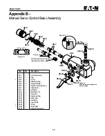
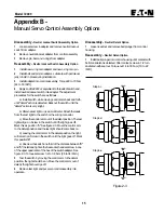
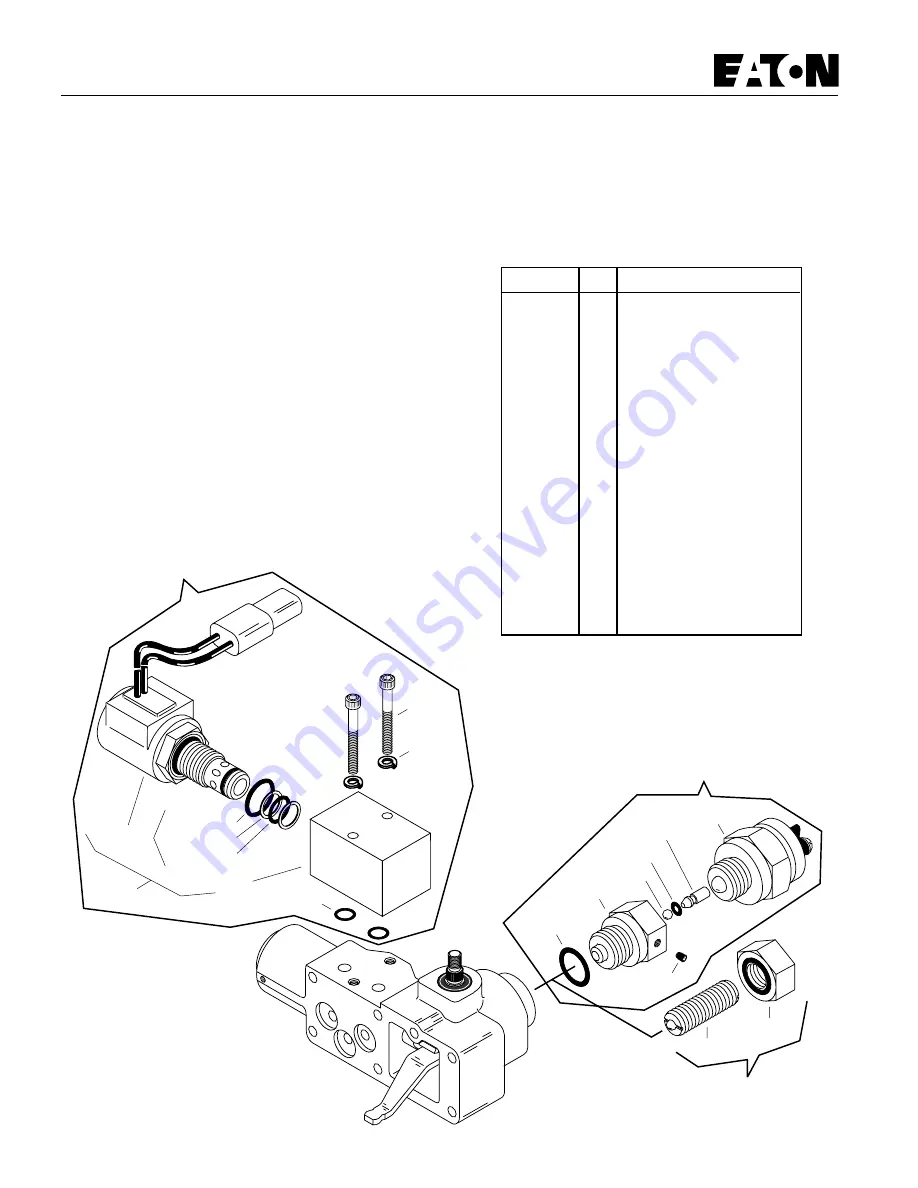
48-18
48-19-1
48-19-2
48-19
48-20
48-21
48-28
48-30
48-29
48-27
48-22
48-23
48-24
48-25
48-26
48-19-2A
48-19-2B
48-19-2C
Appendix B -
Manual Servo Control Assembly Options
Disassembly -
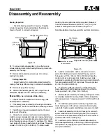
Destroke Valve Assembly Option
1
Remove the two cap screws and lock washers from
manifold. Removing destroke valve assembly and two o-rings.
2
Remove destroke valve from manifold in order to remove
o-rings and back-up washers. Note: in order to remove
destroke valve the solenoid may need to be removed from core
first (not shown).
Reassembly -
Destroke Valve Assembly Option
1
Install new o-rings and back-up washers onto destroke
valve.
2
Install destroke valve into manifold by hand until top o-ring
is met by manifold. Then wrench tighten to 34 N•m [25 lbf•ft. ]
max. Loosen Nut retaining coil to reposition if necessary and
re-torque 5,4 to 7 N•m [4 to 5 lbf•ft.].
3
Lubricate the two o-rings and install onto manifold. Install
destroke valve assembly onto control assembly. Retain with
lock washers and cap screws. Torque 3 to 3,5 N•m [27 to 31
lbf•in.].
Destroke Valve
Assembly
Option
Neutral Detent
Option
Neutral Lockout
Switch Option
Item
Qty.
Description
48-18
2
O-ring
48-19
1
Destroke Valve Assy.
48-19-1
1
Manifold
48-19-2
1
Destroke Valve
48-19-2A
1
O-ring
48-19-2B
2
Back-up Washer
48-19-2C
1
O-ring
48-20
2
Lock Washer
48-21
2
Cap Screw
48-22
1
O-ring
48-23
1
Adapter, Neutral Lockout
48-24
1
Ball
48-25
1
O-ring
48-26
1
Pin
48-27
1
Set Screw
48-28
1
Neutral Lockout Switch
48-29
1
Ball Plunger
48-30
1
Nut, Seal


