76
Eaton 9155 UPS (8–15 kVA) User’s Guide 164201553—Rev H0
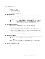
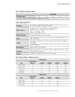
The UPS is now bypassed, with the load powered by utility power.
Verify the load has been transferred to bypass by viewing the output meters screen.
4.
Command the UPS off.
Press the
OPERATION
Eaton 9355 UPS (20/30 kVA) Installation and Operation Manual
S
164201626 Rev C
74
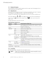
Display Functions
As the default or after 15 minutes of inactivity, the LCD displays the selectable
startup screen. The default is the Eaton logo and can be changed to the Mimic screen
in the User Settings menu.
The backlit LCD automatically dims after a long period of inactivity. Press any button
to restore the screen.
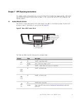
Use the two middle buttons ( and ) to scroll through the menu structure. Press the
button to enter a submenu. Press the
button to select an option. Press the
ESC
button to cancel or return to the previous menu.
The following table shows the basic menu structure.
Table 6. Menu Map for Display Functions
Main Menu
Submenu
Display Information or Menu Function
UPS Status
UPS off / System normal / UPS supporting load / UPS on battery / UPS on bypass / Active alarm
list / Battery status
For parallel systems: System normal / Battery floating UPS in Parallel mode / Parallel Unit
Number x / Units on CAN Bus / Units on load
Event Log
Displays up to 127 events and alarms
Measurements
Parallel System
(parallel UPSs only)
Voltage [by unit] / Voltage [Parallel total] / Output Voltage: L-N / Output Voltage L-L / Output
Current / Output Frequency / Output Power
Output
L-N and L-L / Current / Frequency / Power (kW/kVA/pf)
Battery
Voltage / Current / Runtime
Input
L-N and L-L / Current / Frequency
Bypass
L-N and L-L / Frequency
Control
Go to Bypass Mode
Transfers the UPS to internal Bypass mode
When this command is active, the option changes to Go to Normal Mode.
Start Battery Test
Initiates a battery test
Display Test
Four different selectable tests for the front panel functions: the LEDs cycle through, the alarm
beep sounds, the backlight turns off and on, and the pixels scroll through to test the LCD.
Settings
User Settings
See Table 7 for detail.
Service Settings
This screen is password-protected.
Identification
UPS Type / Part Number / Serial Number / Firmware / Display / CAN Bridge
Turn UPS ON/OFF
ON and OFF Options
button on the front display, scroll to the UPS On/Off menu. Press the
OPERATION
Eaton 9355 UPS (20/30 kVA) Installation and Operation Manual
S
164201626 Rev C
74
Display Functions
As the default or after 15 minutes of inactivity, the LCD displays the selectable
startup screen. The default is the Eaton logo and can be changed to the Mimic screen
in the User Settings menu.
The backlit LCD automatically dims after a long period of inactivity. Press any button
to restore the screen.
Use the two middle buttons ( and ) to scroll through the menu structure. Press the
button to enter a submenu. Press the
button to select an option. Press the
ESC
button to cancel or return to the previous menu.
The following table shows the basic menu structure.
Table 6. Menu Map for Display Functions
Main Menu
Submenu
Display Information or Menu Function
UPS Status
UPS off / System normal / UPS supporting load / UPS on battery / UPS on bypass / Active alarm
list / Battery status
For parallel systems: System normal / Battery floating UPS in Parallel mode / Parallel Unit
Number x / Units on CAN Bus / Units on load
Event Log
Displays up to 127 events and alarms
Measurements
Parallel System
(parallel UPSs only)
Voltage [by unit] / Voltage [Parallel total] / Output Voltage: L-N / Output Voltage L-L / Output
Current / Output Frequency / Output Power
Output
L-N and L-L / Current / Frequency / Power (kW/kVA/pf)
Battery
Voltage / Current / Runtime
Input
L-N and L-L / Current / Frequency
Bypass
L-N and L-L / Frequency
Control
Go to Bypass Mode
Transfers the UPS to internal Bypass mode
When this command is active, the option changes to Go to Normal Mode.
Start Battery Test
Initiates a battery test
Display Test
Four different selectable tests for the front panel functions: the LEDs cycle through, the alarm
beep sounds, the backlight turns off and on, and the pixels scroll through to test the LCD.
Settings
User Settings
See Table 7 for detail.
Service Settings
This screen is password-protected.
Identification
UPS Type / Part Number / Serial Number / Firmware / Display / CAN Bridge
Turn UPS ON/OFF
ON and OFF Options
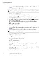
button to turn the
UPS off.
Rear fan is running signifying load is being supplied utility power on bypass.
5.
Switch all of the UPS battery circuit breakers to the Off position.
6.
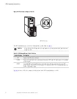
Turn the maintenance bypass switch on the back of the UPS to the Bypass position (see
).
77..44..22
TTrraannssffeerr tthhee llooaadd ffrroom
m m
maaiinntteennaannccee bbyyppaassss ttoo tthhee U
UP
PS
S
1.
Turn the maintenance bypass switch on the back of the UPS to the SERVICE position (see
2.
Switch all of the UPS battery circuit breakers to the ON position.
3.
Wait 1.5 to 2 minutes for the internal startup process to complete.
Wait until the bypass indicator illuminates and the two front fans are operating before proceeding to the
next step.
Verify the output voltage is present on the meters screen.
4.
Turn the maintenance bypass switch on the back of the UPS to the UPS position to return to Normal mode
(see
When the green UPS normal indicator illuminates, the UPS is powering the load.
Verify the load is transferred to the UPS by viewing the output meters screen.
5.
Reinstall any ConnectUPS Web/SNMP or PXGX cards, secure with retained hardware and connect cables.
77..55
C
Coonnffiigguurriinngg tthhee U
UP
PS
S ffoorr EEB
BM
Mss
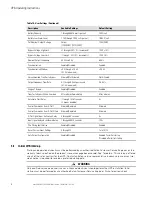
To ensure maximum battery runtime, configure the UPS for the correct number of EBMs:
1.
Press any button on the front panel display to activate the menu options.
2.
Using the
button, scroll to the Settings menu.
3.
Press the
button twice to select the User Settings menu.
4.
Using the
button, scroll to the Battery Setup option and press the
button.
5.
The “Number of Battery Strings will appear”, using the
or
buttons to select the number of strings
according to your UPS configuration:
All 2-High UPS and EBM Cabinets*
Number of Strings
UPS + 1 EBM
6
UPS + 2 EBMs
10
UPS + 3 EBMs
14
UPS + 4 EBMs
18
All 3-High UPS and EBM Cabinets*
Number of Strings
Summary of Contents for 9155 UPS
Page 1: ...p n 164201553 Revision H0 8 15 kVA User s Guide Eaton 9155 UPS ...
Page 8: ...viii Eaton 9155 UPS 8 15 kVA User s Guide 164201553 Rev H0 List of Tables ...
Page 14: ...6 Eaton 9155 UPS 8 15 kVA User s Guide 164201553 Rev H0 Introduction ...
Page 18: ...10 Eaton 9155 UPS 8 15 kVA User s Guide 164201553 Rev H0 Safety Warnings ...
Page 60: ...52 Eaton 9155 UPS 8 15 kVA User s Guide 164201553 Rev H0 UPS System Installation ...
Page 66: ...58 Eaton 9155 UPS 8 15 kVA User s Guide 164201553 Rev H0 UPS Wiring Diagrams and Schematics ...
Page 86: ...78 Eaton 9155 UPS 8 15 kVA User s Guide 164201553 Rev H0 UPS Operating Instructions ...
Page 98: ...164201553H0 164201553 H0 ...

