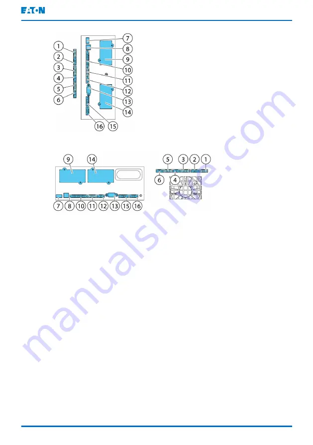
Figure 26. Communication interfaces in the 15/20 kW standard and C-model frames
Figure 27. Communication interfaces in the 30/40 kW frame
1
TB11, not used
9
MiniSlot 1
2
TB10, not used
10
TB1, signal input 1-5
3
TB9, not used
11
TB2, not used
4
TB8, external CAN termination
12
TB3, not used
5
TB7, external CAN
13
Serial COM port RS-232
6
TB6, pull chain bus
14
MiniSlot 2
7
USB1, USB host (connection to
accessories)
15
TB4, EPO
8
USB2, USB device (connection to
computer)
16
TB5, relay output
for the location of communication interfaces in
91PS/93PS UPS.
Eaton 91PS/93PS UPS 8–40 kW
User's and installation guide
©
Eaton Corporation plc 2018. All rights reserved.
Revision: 005
Document ID: P-164000493
72 (117)


