7.8
Turning the UPS from the double conversion mode
to the maintenance bypass mode
Only trained personnel who are familiar with the behavior and functions of the
UPS are allowed to operate the internal MBS. A full UPS wiring diagram with
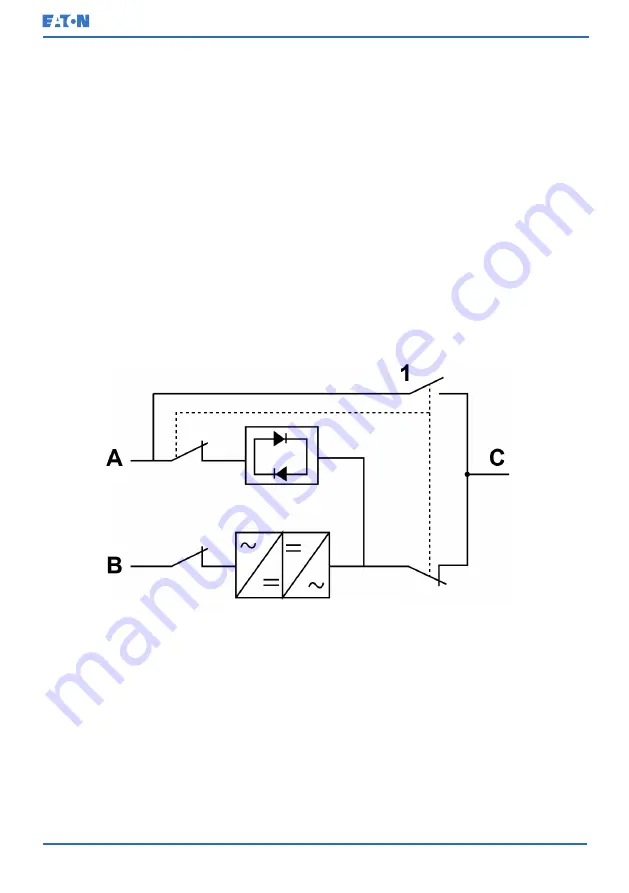
MBS switch is presented in the schematic diagram.
NOTE: The internal MBS and static bypass must be supplied by the same
source.
The MBS has 3 positions: UPS, Test and Bypass. When the MBS is turned to the
Test position, the UPS is already turned to maintenance bypass and it no longer
provides protected input to the load, but enables testing of the UPS internal
functionality.
To turn the UPS to maintenance bypass:
1.
Follow the normal start position:
Figure 39: Normal positions of the MBS switches and rectifier disconnect switch
(must be located in the site wiring)
A
Static bypass input
1
Maintenance Bypass input switch
(MBS)
B
Rectifier input
C
Out
2.
Do the transfer from the double conversion mode to the bypass mode as
instructed in
Section 7.4.3 Transfer from the double conversion mode to the
. Remember to verify the transfer before proceeding to the next
step.
© Eaton Corporation plc 2020. All rights reserved.
Revision: 006
Document ID: P-164000493
104
(126)
Eaton 91PS/93PS UPS 8–40 kW
User’s and Installation Guide


