background image

Using Features and Options

6-5

EATON

Powerware

®

9315 UPS (200–300 kVA) Operation Manual

S

164201036 Rev F

powerware.com

6.4 Battery Cabinets

You can enhance the protection time provided by your UPS by adding one or more battery

cabinets. The battery cabinets provided by the UPS manufacturer are equipped with sealed

lead-acid, maintenance-free batteries in a cabinet that matches the UPS. Each battery

cabinet contains a battery circuit breaker. Several battery capacities are available.

The UPS battery cabinets can be paralleled. With this capability, you can increase your

battery backup time by adding battery cabinets to your UPS system. The Powerware 9315

can support up to four battery cabinets.

6.5 External Battery Disconnect

A breaker is located inside each battery cabinet supplied by the UPS manufacturer.

However, due to space limitations, your battery cabinets may not be located in the same

area as your UPS. An optional external DC circuit breaker provides a manual means of

disconnecting a battery that is located remotely from the UPS. The circuit breaker is

enclosed in a wall-mounted box. You can install it anywhere between the remote DC

supply and the UPS, according to national and local codes.

The breaker switch should be set to ON for normal UPS operation when DC power is

available at the UPS. When service personnel are performing maintenance on the UPS or

battery cabinet, the switch should be set to OFF.

NOTE

There is no DC disconnect device within the UPS.

NOTE

The DC input to the UPS is protected by internal fuses F21 and F22.

NOTE

The UPS DC disconnect trip signal from TB4, points 1 and 2 (shunt trip) or TB4,

points 1 and 3 (UV trip) must be connected to the DC source disconnect device(s).

Summary of Contents for 9315

Page 1: ...Powerware 9315 UPS 200 300 kVA Operation Manual...

Page 2: ...ted in a commercial environment This equipment generates uses and can radiate radio frequency energy and if not installed and used in accordance with the instruction manual may cause harmful interfere...

Page 3: ...Emergency Load Off 2 5 2 4 6 Automatic Battery Charge Current Limit 2 5 2 4 7 Installation Features 2 5 2 5 Options and Accessories 2 5 2 5 1 Battery 2 5 2 5 2 External Battery Disconnect 2 5 2 5 3 P...

Page 4: ...ff Button 5 3 5 5 Reading the Status Indicators 5 4 5 6 Using the Menu Options 5 4 6 Using Features and Options 6 1 6 1 Building Alarm Monitoring 6 1 6 2 Summary Alarm Contacts 6 2 6 3 Remote Monitor...

Page 5: ...ges 7 15 7 7 5 Program Unit Name 7 16 7 7 6 Adjust Output Voltage 7 16 7 7 7 Change Password 7 16 7 7 8 Battery Test Setup 7 17 7 7 9 Modify Low Battery Time 7 18 7 8 Calibration Mode 7 18 7 9 Compute...

Page 6: ...r Powerware 9315 300 480 480V UPS 5 5 Figure 5 4 Load Amps Meters Screen 5 6 Figure 5 5 Event History Log Screen 5 7 Figure 5 6 Active System Events Screen 5 8 Figure 5 7 Unit Statistics Screen 5 9 Fi...

Page 7: ...omatically and require very little attention during normal operation However you should read and understand the procedures described in this manual to ensure trouble free operation In particular you s...

Page 8: ...optional accessories including dimensions and connection points Visit www powerware com or contact your Eaton service representative for information on how to obtain copies of this manual 1 3 Getting...

Page 9: ...the risk of fire or electric shock install this UPS in a temperature and humidity controlled indoor environment free of conductive contaminants Ambient temperature must not exceed 40 C 104 F Do not o...

Page 10: ...re 2 1 shows a typical Powerware 9315 UPS system Input Transformer Cabinet Output Transformer Cabinet optional PDM Cabinet optional requires 480 208 transformer UPS Cabinet Battery Cabinet optional Fi...

Page 11: ...ctifier Charger AC Input to Bypass Input Filter UPS Cabinet Digital Metering Static Switch Bypass Contactor Output Contactor Output Transformer Inverter Rectifier Charger Power Processing Unit PPU AC...

Page 12: ...powered communication with optional X Slot cards The X Slot cards support several protocols such as SNMP HTTP and Modbus See Chapter 7 Communication for additional information Computer Interface Seri...

Page 13: ...sing and monitoring control wire must be installed in accordance with Class 2 wiring methods Bottom entry is provided for Class 2 wiring 2 5 Options and Accessories Contact a Powerware sales represent...

Page 14: ...g you to monitor the operational status and alarm condition of the UPS from virtually any location within your facility You can install multiple RMPs at remote locations to increase your monitoring ca...

Page 15: ...former is contained in a separate cabinet 2 5 10 Modem An optional modem is available for use with the UPS Remote Notification feature described in Remote Notification on page 7 19 Refer to the manual...

Page 16: ...Off position PHASE The word phase RISK OF ELECTRIC SHOCK Indicates that a risk of electric shock is present and the associated warning should be observed CAUTION REFER TO OPERATOR S MANUAL Refer to yo...

Page 17: ...es are automatic and transparent to the critical load The UPS switches operating modes in response to these system events A command is an intervention that is externally initiated by an operator or by...

Page 18: ...t of specification the UPS automatically switches to Battery mode to support the critical load with no interruption When utility power returns the UPS returns to Normal mode If the UPS system becomes...

Page 19: ...s K4 Transformer K3 Open CB1 Figure 3 2 Path of Current Through the UPS in Bypass Mode You can transfer the UPS from Normal mode to Bypass mode manually However the UPS switches automatically to Bypas...

Page 20: ...en operating in Battery mode Bypass Input Rectifier Input Output Path of electrical power Battery Rectifier Inverter Bypass K4 Transformer K3 Closed CB1 Figure 3 3 Path of Current Through the UPS in B...

Page 21: ...e Control Panel The Monitor Panel on the left front of the UPS continually indicates the present mode of UPS operation This panel contains an LCD screen backlit status indicators and the LOAD OFF butt...

Page 22: ...Understanding UPS Operation 3 6 EATON Powerware 9315 UPS 200 300 kVA Operation Manual S 164201036 Rev F powerware com This page intentionally left blank...

Page 23: ...reliminary startup verifies all electrical interconnections to ensure the installation was successful and the UPS system operates properly 4 1 Using the Control Panel The Control Panel is inside the r...

Page 24: ...turns on when the START switch is activated and the proper voltage is at the input terminals The PUSH TO RESET button is described in Resetting the UPS System after Load Off on page 11 2 The START swi...

Page 25: ...remains on and an alarm sounds 2 When the transfer is complete the LCD screen reads On Bypass move the CB1 switch to OFF The bypass source supplies the critical load and the power processor de energiz...

Page 26: ...Starting and Stopping the UPS 4 4 EATON Powerware 9315 UPS 200 300 kVA Operation Manual S 164201036 Rev F powerware com This page intentionally left blank...

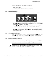
Page 27: ...tangular area on the front of the UPS see Figure 5 1 1 2 3 4 Figure 5 1 UPS Monitor Panel The Monitor Panel contains a flat liquid crystal display LCD screen 1 a horizontal row of buttons 2 a vertical...

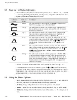
Page 28: ...of the current active alarms and the third line shows any notices the UPS has posted For more information about alarms and notices see Chapter 10 Responding to System Events B The battery charge box...

Page 29: ...to test the lamps behind the status indicators Press the button to toggle the use of the and buttons between the menu box and the information area 5 3 Adjusting the Contrast Use the buttons to adjust...

Page 30: ...tention The LCD screen shows the highest priority active alarms All alarms are accompanied by an audible horn To silence the horn press the and buttons simultaneously The Alarm indicator may be lit al...

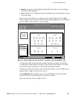
Page 31: ...ass Battery VAB 480 VBC VCA KW 379 KVA 399 IA IB IC FREQ 60 0 PF 0 95 V 540 I 000 Meters 480 480 480 480 480 VAB 480 VBC VCA 480 480 IA IB IC 361 361 361 IN 000 VAB 480 VBC VCA 480 480 FREQ 60 0 KVA 3...

Page 32: ...1036 Rev F powerware com Uninterruptible Power System System Normal Alarm None Notice None Meters System Load Amps Events Statistics Graphics Setup Meters Output Current 125 100 75 50 25 0 Phase A Pha...

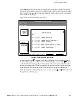
Page 33: ...1 16 41 22 4 16 41 25 5 16 41 26 8 16 41 27 8 16 41 30 4 16 41 29 1 COMMAND Keyswitch On STATUS Auto Mode COMMAND Rectifier Commanded On STATUS Inverter On STATUS Rectifier On STATUS Inverter Contacto...

Page 34: ...ed first As events clear they are removed from the Active System Events listing Figure 5 6 shows the Active System Events screen Uninterruptible Power System Alarm On Battery Shutdown Imminent Notice...

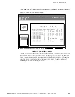
Page 35: ...rm 1 Building Alarm 2 Building Alarm 3 Building Alarm 4 Building Alarm 5 Building Alarm 6 UPS Bypass Battery Generator Logic Availability UPS Bypass 0 1 0 0 2 2 3 2 3 3 0 0 0 0 11 9 8 5 8 9 0 99 0 81...

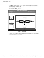
Page 36: ...urrent through the UPS Figure 5 8 shows the Mimic screen Uninterruptible Power System UPS System Normal Alarm None Notice None Events Statistics Graphics Setup Meters Graphics Mimic 04 NOV 1997 14 23...

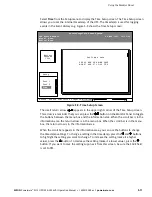
Page 37: ...The small return arrow appears in the upper right corner of the Time Setup screen This arrow is a reminder that you can press the button on the Monitor Panel to toggle the buttons between the menu box...

Page 38: ...ODE TERMINAL Port 2 04 NOV 1997 14 23 45 100 Percent Battery Figure 5 10 Setup Serial Port 1 Screen The small return arrow appears in the upper right corner of the Port Setup screen This arrow is a re...

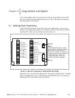
Page 39: ...solated normally open contact or switch rated at 24 Vdc 20 mA minimum connected between the alarm input terminal and common terminal as shown All control wiring relay and switch contacts are customer...

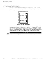
Page 40: ...11 12 13 14 15 TB2 Figure 6 2 Summary Alarm Contacts You can specify that each contact be either normally closed NC or normally open NO If the state of the contact changes from the state you specify...

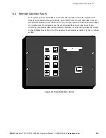
Page 41: ...on within your facility up to 500 ft from the UPS Each RMP contains backlit status indicators and a local horn You can flush mount or surface mount an RMP on a desktop wall or wherever you have a seri...

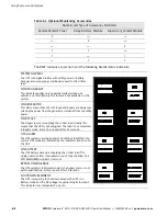
Page 42: ...bypass are being sup plied by the power from the generator instead of from the utility power ON BYPASS The bypass source is supplying the critical load Usually this means that the UPS is not energize...

Page 43: ...ide each battery cabinet supplied by the UPS manufacturer However due to space limitations your battery cabinets may not be located in the same area as your UPS An optional external DC circuit breaker...

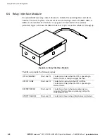
Page 44: ...hows the RIM with its four 15 pin connectors labeled J1 through J4 Figure 6 4 Relay Interface Module The RIM can provide the following signals UPS AVAILABLE Pins 1 and 12 Contacts are closed when the...

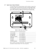
Page 45: ...6 4 for the number of accessories permitted Figure 6 5 shows the SCM input connections on TB1 and output connections on TB2 TB2 Figure 6 5 Supervisory Contact Module The SCM provides signals for the f...

Page 46: ...Using Features and Options 6 8 EATON Powerware 9315 UPS 200 300 kVA Operation Manual S 164201036 Rev F powerware com This page intentionally left blank...

Page 47: ...tor Panel Relay Interface Module or Supervisory Contact Module The Communication Panel also contains terminals TB1 and TB2 for connecting your equipment to the UPS The X Slot communication bay used fo...

Page 48: ...ation bay and is compatible with the following cards ConnectUPS X Web SNMP Card provides remote monitoring through a Web browser interface e mail and a network management system using SNMP connects to...

Page 49: ...wer Management Software To begin installing LanSafe software see the instructions accompanying the Powerware Software Suite CD LanSafe software uses an RS 232 serial link to communicate with the UPS a...

Page 50: ...485 Data 8 485 RS 485 Data 9 RTN Return NOTE The X Slot communication bay is connected internally to the DB 25 port by default the DB 25 is disabled for other uses Contact your Eaton service represen...

Page 51: ...Ground 2 TXD Transmit Data Input to UPS 3 RXD Receive Data Output from UPS 4 RTS Request to Send Input to UPS 5 CTS Clear to Send Output from UPS 6 DSR Data Set Ready Output from UPS 7 RTN Return 8 1...

Page 52: ...le Power System UPS System Normal Alarm None Notice None 03 NOV 1997 14 23 45 Events Meters Setup Serial Port 1 Rate 9600 Data Stop 8 1 Handshaking XON XOFF Save NO Time Mode TERMINAL Port 2 Battery 1...

Page 53: ...tem events are logged immediately as they occur System Configuration Mode Allows you to set building alarms battery tests etc Check with your sales or service representative for availability Calibrati...

Page 54: ...ial port ignoring all inputs from handshaking lines 7 5 4 2 XON XOFF If handshaking is enabled the UPS uses special characters XON and XOFF to handshake with the host terminal The XON character is def...

Page 55: ...S Second 2 digits hh Hundredths of Second 2 digits KYWD MESSAGE Keyword ALARM NOTICE COMMAND or STATUS System Diagnostic Information CR Carriage Return Character ASCII 13 LF Line Feed ASCII 10 An alar...

Page 56: ...ents in chronological order with the most recent event listed last Figure 7 6 shows a sample Event History Log printout Event History Log Event Description MAY 12 12 12 12 12 12 12 12 JUN 04 16 41 19...

Page 57: ...ws the same information for the power being output by the UPS The Bypass area shows the phase to phase voltage of the bypass source The Battery area displays the DC voltage V and the DC current I Figu...

Page 58: ...98 0000 FEB 12 23 45 498 0 0 98 0000 MAR 12 23 41 000 0 0 00 0003 APR 9 23 45 496 2 0 98 0000 Battery Test Log Date Time Volts Health Data Figure 7 8 Battery Test Log The Date Time field is the date a...

Page 59: ...e prompted to enter the password for this mode Please Enter Password The default password is EXIDE1 You may modify this password using the change password function in the following menu When the valid...

Page 60: ...to Disable Building Alarm Number Enter CR for No Change Enter Selection Where Function indicates the function the building alarm is being programmed for The line following the Enabled Building Alarm...

Page 61: ...prompt the following text appears Building Alarm Active Message Building Alarm 1 default message Enter New Message or CR for No Change At this level you can enter a custom message 30 characters maxim...

Page 62: ...o center the text portion of the name the appropriate number of leading spaces should be included when entered 7 7 6 Adjust Output Voltage If Adjust Output Voltage is selected from the main menu the f...

Page 63: ...0 23 Enter Minute of Test 0 59 NOTE Press ENTER after each entry CR with no entry will return to Battery Test Setup Menu Enter the information at the prompt with a carriage return to schedule the batt...

Page 64: ...ld service personnel to calibrate system meters Factory test engineers calibrate the UPS meters prior to shipping so the UPS arrives at your site correctly calibrated After use field service personnel...

Page 65: ...te Notification provides the user with the option of receiving alarms and notices at a remote location Using the Terminal mode the user calls the UPS to perform basic monitoring In the event of a UPS...

Page 66: ...Communication 7 20 EATON Powerware 9315 UPS 200 300 kVA Operation Manual S 164201036 Rev F powerware com This page intentionally left blank...

Page 67: ...terior is unsafe until the DC power source is disconnected and the electrolytic capacitors are discharged After disconnecting the utility power and the DC power authorized service personnel should wai...

Page 68: ...erforming Preventive Maintenance The UPS requires very little preventive maintenance However the UPS should be inspected periodically to verify that it is operating normally and that the batteries are...

Page 69: ...information about service offerings BATTERY maintenance Contact your nearest field service office for battery maintenance Battery replacement and maintenance should be performed only by authorized se...

Page 70: ...Maintaining the UPS System 8 4 EATON Powerware 9315 UPS 200 300 kVA Operation Manual S 164201036 Rev F powerware com This page intentionally left blank...

Page 71: ...ry specifications for the UPS Table 9 2 System Input Operating Input Voltage Nominal 10 15 480 Vac for operation from 408 Vac to 528 Vac 60 Hz only 400 Vac for operation from 340 Vac to 440 Vac 50 60...

Page 72: ...unning Synchronous to Bypass Bypass within voltage limits of 5 8 of output setting bypass within 0 5 Hz Frequency Slew Rate 1 Hz per second maximum adjustable Overload Capability 125 for 10 minutes 15...

Page 73: ...e Sealed maintenance free high rate discharge lead acid cells Nominal Battery String Voltage 480 Vdc 240 cells for Powerware 9315 225 and Powerware 9315 300 420 Vdc 210 cells for Powerware 9315 200 an...

Page 74: ...Product Specifications 9 4 EATON Powerware 9315 UPS 200 300 kVA Operation Manual S 164201036 Rev F powerware com This page intentionally left blank...

Page 75: ...n any mode other than Normal Only the Normal indicator is visible during normal UPS operation The others light to indicate alarms or events When an alarm occurs you should first check these indicators...

Page 76: ...Failure Phase A Current Limit Phase B Current Limit Phase C Current Limit Bypass Control Failure Load Transferred to Bypass Inverter Cont K3 Failure Inverter Failure Load Off Inverter Cont K3 Open Byp...

Page 77: ...put AC Over Frequency Clear Input AC Over Frequency Rct Over Temperature Warning Clear Rct Over Temp Warning Input AC Under Frequency Clear Input AC Under Frequency Rct Temp Sensor Failure Clear Rct T...

Page 78: ...Frequency Clear Output Under Frequency Fan Failure Clear Fan Failure 3W AC Over Voltage Clear 3W AC Over Voltage 3W AC Under Voltage Clear 3W AC Under Voltage 3W Over Frequency Clear 3W Over Frequency...

Page 79: ...load is lost when you press this button You should use this feature only in an emergency or when you want to de energize the critical load To restart the UPS after pressing the LOAD OFF button follow...

Page 80: ...ton is a small white button on the UPS Control Panel The PUSH TO RESET button pops out and the CB1 switch trips when the LOAD OFF button on the Monitor Panel is activated To reset the UPS system 1 Pre...

Page 81: ...oduct b if the Product is moved to a new location by someone other than an authorized Eaton Customer Service Engineer in the USA or Agent outside of the USA or c if the Product s serial numbers have b...

Page 82: ...Warranty W 2 EATON Powerware 9315 UPS 200 300 kVA Operation Manual S 164201036 Rev F powerware com This page intentionally left blank...

Page 83: ......

Page 84: ...164201036F 164201036 F...

Reviews: