Sync Control for Eaton 9395P and 93PM
22
User’s and Installation Guide
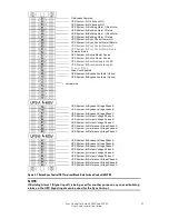
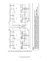
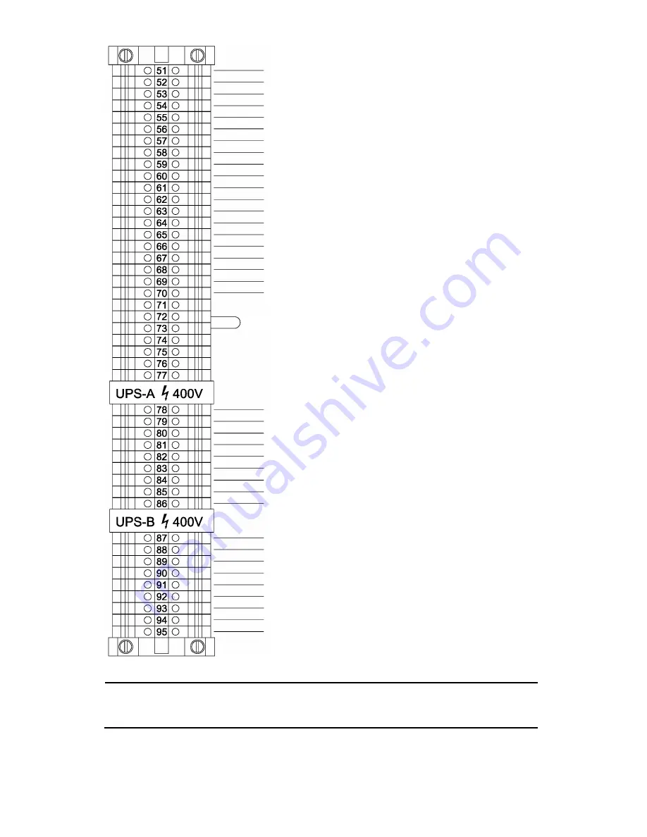
Figure 3-7 Eaton Sync Control TB1 Terminal Block Detail when Used with 93PM
NOTE:
If Building Alarm 1 (Signal input1) is being used for another purpose, any unused building
alarm on the UPS Signal inputs can be used for the Sync Control.
On Bypass Common
UPS System-A
─
On Bypass NO
UPS System-B
─
On Bypass NO
UPS System-B
─
Reference Voltage Phase B
UPS System-B
─
Reference Voltage Phase A
UPS System-B
─
Reference Voltage Phase C
UPS System-A
─
Building Alarm 1 (See Note)
UPS System-B
─
Building Alarm 1 (See Note)
UPS System-A
─
Sync Control Alarm NO
UPS System-A
─
Sync Control Alarmt Return
UPS System-B
─
Sync Control Alarm NO
UPS System-B
─
Sync Control Alarm Return
Common Return
UPS System-A
─
Active Master Source
UPS System-B
─
Active Master Source
UPS System-A
─
Synchronized to Load B
UPS System-B
─
Synchronized to Load A
Common Return
Load Sync Enabled
Jumper wire
UPS System-A
─
Building Alarm 1 Return
UPS System-B
─
Building Alarm 1 Return
UPS System-B
─
Output Voltage Phase B
UPS System-B
─
Output Voltage Phase A
UPS System-B
─
Output Voltage Phase C
UPS System-B
─
Bypass Voltage Phase B
UPS System-B
─
Bypass Voltage Phase A
UPS System-B
─
Bypass Voltage Phase C
UPS System-
A─
Reference Voltage Phase B
UPS System-
A─
Reference Voltage Phase A
UPS System-
A─
Reference Voltage Phase C
UPS System-
A─
Output Voltage Phase B
UPS System-
A─
Output Voltage Phase A
UPS System-
A─
Output Voltage Phase C
UPS System-
A─
Bypass Voltage Phase B
UPS System-
A─
Bypass Voltage Phase A
UPS System-
A─
Bypass Voltage Phase C
UPS System-A
─
Bypass Available (Option)
UPS System-B
─
Bypass Available (Option)


