INTRODUCTION
EATON
Powerware
®
9395 UPS (650–825 kVA) Installation and Operation Manual
S
164201725 Rev 2
www.powerware.com
1−3
S
Alarm Contact
– One alarm contact is provided for connection to equipment at the
facility, such as a light, an audible alarm, or a computer terminal. The equipment
connected to this contact alerts you to a UPS alarm. See Chapter 8,
Communication," for additional information.
S
X−Slot Communication Bays
– Four communication bays are standard equipment.
One to four optional X−Slot
®
connectivity cards can be installed in the UPS module
at any time. X−Slot cards are quickly installed at the front of the UPS and are
hot−pluggable. See Chapter 8, Communication," for additional information.
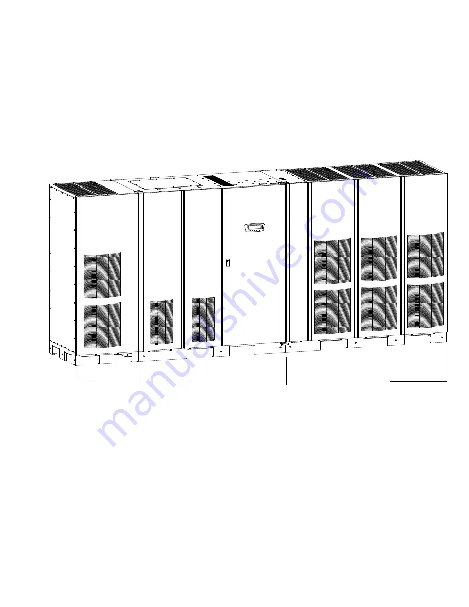
ISBM SECTION
UPM SECTION
FI−UPM
Figure 1-2. Powerware 9395 UPS (650–825 kVA) with the Field Installed UPM
1.1.4
Advanced Battery Management
A three−stage charging system increases battery service life by optimizing recharge
time, and protects batteries from damage due to high current charging and inverter
ripple currents. Charging at high currents can overheat and damage batteries.
1.1.5
Power Management Software
Powerware LanSafe
®
Power Management Software is bundled as part of the
Software Suite CD shipped with the UPS. See Chapter 8, Communication," for
additional information.


