UPS SYSTEM INSTALLATION
Eaton 9395 UPS (450–825 kVA) Installation and Operation Manual
S
164201725 Rev 4
www.eaton.com/powerquality
4-30
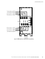
(See Figure 4‐26 for Detail AA.)
DC Input from B (E4)
– (E5)
DC Input from Battery
AC Input to UPS Rectifier
(A, B, C)
AC Input to UPS Bypass
(A, B, C)
(See Figure 4‐26 for Detail AA.)
ISBM
(See Figure 4‐32 or
Figure 4‐33 for Detail BB.)
(See Figure 4‐32 or
Figure 4‐33 for Detail BB.)
AC Output to
Critical Load
Phase C
(E11)
Phase A (E9)
Phase B
(E10)
A
B
C
N
(E12)
Neutral
NOTE
AC Input to Bypass terminals are not applicable to an IOM configuration.
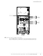
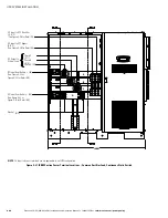
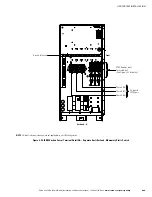
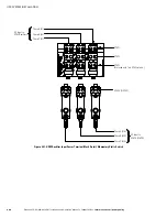
Figure 4‐25. ISBM Section Power Terminal Locations – Common Rectifier Feed, Momentary Static Switch


