UPS Operating Instructions
Eaton
®
Power Xpert
®
9395C UPS Installation and Operation Manual P-164000821—Rev 01
www.eaton.com/powerquality
7-5
7.3.1
Status Indicators
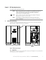
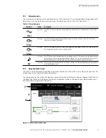
The symbols on the bottom of the control panel are status indicators. These colored light emitting diode (LED)
lamps work with the alarm horn to let you know the operating status of the UPS. See Table 7-1.
7.3.2
Using the Touch Screen
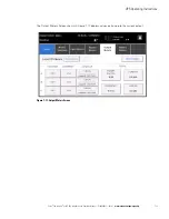
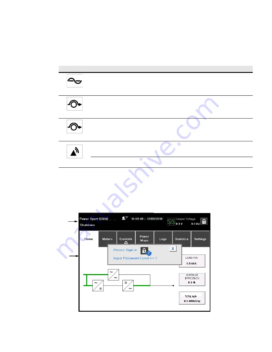
The touch screen control panel provides an operator interface with the UPS system. Figure 7-5 identifies the
display areas discussed in the following sections.
Touching an area on the screen that requires a password brings up the Sign In Request pop-up. Touch the X in
the upper right corner of the pop-up, then touch the padlock symbol in the upper right corner to obtain the
password request pop-up (see Figure 7-6).
Figure 7-5. Parts of the Touch Screen
Table 7-1. Status Indicators
Indicator
Status
Description
Green
Lit Steady
The UPS is in Online mode, operating normally. The power module is supplying power to the critical
load.
Yellow
Lit Steady
The UPS is in Battery mode. Because Battery mode is a normal condition of the UPS, the Online
indicator also remains illuminated.
Yellow
Lit Steady
The UPS is in Bypass mode. The critical load is supported by the bypass source. The Online indicator is
not illuminated when the system is in Bypass mode.
Red
Lit Steady
The UPS has an active alarm and requires immediate attention. The screen shows the highest priority
active alarms. All alarms are accompanied by an audible horn. To silence the horn, press any control
panel pushbutton once. The Alarm indicator may be illuminated along with other indicators.
Lit Flashing
There is a new UPS alarm condition. The indicator flashes until acknowledged by pressing anywhere
on the control panel once.
A
B
Summary of Contents for 9395C-1000/1000
Page 2: ......
Page 23: ...Section I Installation ...
Page 24: ......
Page 93: ...Section II Operation ...
Page 94: ......
Page 155: ......
Page 156: ... P 164000821 1 P 164000821 1 ...

