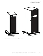
Installation Plan and Unpacking
3-10
Eaton 93E Integrated Transformer Cabinet (ITC) Installation Manual P-164000074—Rev 3
www.eaton.com/powerquality
For external power wiring requirements, including the minimum AWG size of external wiring, see Table 3-4 or
Table 3-5. Wire sizes listed are for copper wiring only.
Table 3-4. External Power Wiring Requirements for the Eaton 93E 30ITC and 93E 60ITC – Single Transformer
Basic Unit Rating
Units
Rating 60 Hz
kVA
30
60
Input/Output Voltage
Volts
480/208
480/208
480 Vac Input to Input Transformer
(3) Phases, (1) Ground
A
Maximum Amps
43
85
Minimum Conductor Size (Phase A, B, and C)
Number per Phase
AWG or kcmil
(each)
#6
(1)
#2
(1)
208 Vac Output from Input Transformer
to
UPS
(3) Phases, (1) Neutral, (1) Ground
B
Maximum Amps
96
192
Minimum Conductor Size (Phase A, B, and C)
Number per Phase
AWG or kcmil
(each)
1/0
(1)
250
(1)
Minimum Conductor Size (Neutral)
Number per Phase
—
AWG or kcmil
(each)
1/0
(2)
250
(2)
Building, Load, and Inter-Cabinet Ground
Minimum Conductor Size (Ground)
Number per Phase
—
AWG or kcmil
(each)
#6
(1)
#2
(1)
NOTE
Callout letters
A
and
B
map to Figure 5-1


