Installation
Eaton 93E Integrated Transformer Cabinet (ITC) Installation Manual P-164000074—Rev 3
www.eaton.com/powerquality
4-21
4.
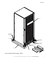
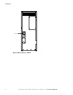
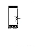
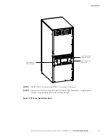
Route the AC utility source input wiring (phase A, B, and C, and Ground) through the conduit and the wire
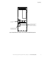
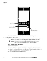
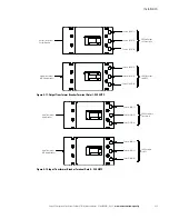
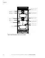
tray (Figure 4-8 or Figure 4-9) on the back of the ITC to the ITC AC input to transformer terminals. See
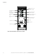
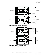
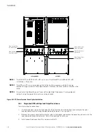
Figure 4-10 or Figure 4-13 for ITC terminal locations. See paragraph 3.2.2, Table 3-4, and Table 3-5 for ITC
wiring and termination requirements.
5.
Connect phase A, B, C, and ground ITC input power wiring from the utility source to the ITC AC input to
transformer terminals and ground terminals. See paragraph 3.2.2 for wiring and termination requirements.
6.
If installing wiring using conduit, continue to Step 7; if using the power terminal cover base channels, skip
to Step 21.
7.
Punch or drill holes in the bottom of the power terminal cover base on the UPS cabinet for the UPS
rectifier input conduit. Refer to the applicable Eaton 93E UPS Installation and Operation manual listed in
paragraph 1.6 for UPS cabinet conduit landing location.
8.
Install conduit between the UPS cabinet and the ITC.
9.
Route the UPS rectifier input wiring (phase A, B, and C, Neutral and Ground) from the ITC through the wire
tray and the conduit to the UPS terminal block on the back of the UPS. See Figure 4-10 or Figure 4-13 for
ITC terminal locations. See paragraph 3.2.2, Table 3-4, and Table 3-5 for ITC wiring and termination
requirements. Refer to the applicable Eaton 93E UPS Installation and Operation manual listed in paragraph
1.6 for their respective terminal locations and termination requirements.
10. Connect phase A, B, C, Neutral, and Ground rectifier input power wiring from the ITC to the UPS rectifier
input, neutral, and ground terminals. See paragraph 3.2.2 for wiring and termination requirements.
11. Connect phase A, B, C, Neutral, and Ground ITC output power wiring to the ITC AC output to UPS, neutral,
and ground terminals. See paragraph 3.2.2 for wiring and termination requirements.
12. Route the UPS output wiring (phase A, B, and C and Ground) from the ITC through the wire tray and the
conduit to the UPS terminal block on the back of the UPS. See Figure 4-10 or Figure 4-13 for ITC terminal
locations. See paragraph 3.2.2, Table 3-4, and Table 3-5 for ITC wiring and termination requirements. Refer
to the applicable Eaton 93E UPS Installation and Operation manual listed in paragraph 1.6 for their
respective terminal locations and termination requirements.
13. Connect phase A, B, C and Ground UPS output power wiring from the ITC to the UPS output and ground
terminals. See paragraph 3.2.2 for wiring and termination requirements.
14. Connect phase A, B, C and Ground ITC output power wiring to the ITC AC output to UPS and ground
terminals. See paragraph 3.2.2 for wiring and termination requirements.
15. Install conduit between the ITC and the critical load or Integrated Accessory Cabinet-Bypass (IAC-D).
Refer to the
Eaton 93E Integrated Accessory Cabinet-Distribution Installation Manual
listed in paragraph
1.6 for conduit and terminal locations and termination requirements.
16. Route the critical load output wiring (phase A, B, and C, Neutral and Ground) through the wire tray and the
conduit on the back of the ITC to the ITC AC output to critical load terminals. See Figure 4-10 or
Figure 4-13 for ITC terminal locations. See paragraph 3.2.2, Table 3-4, and Table 3-5 for ITC wiring and
termination requirements.
17. Connect phase A, B, C, Neutral, and Ground output power wiring from the critical load or IAC-D to the ITC
AC output to critical load, neutral, and ground terminals. See paragraph 3.2.2 for wiring and termination
requirements.
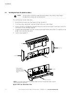
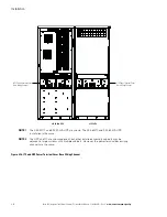
18. Install the power terminal cover top using the provided hardware (see Figure 4-17).
19. Install the power terminal cover right and left sides using the provided hardware (see Figure 4-17).
20. Skip to Step 37.

