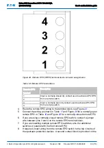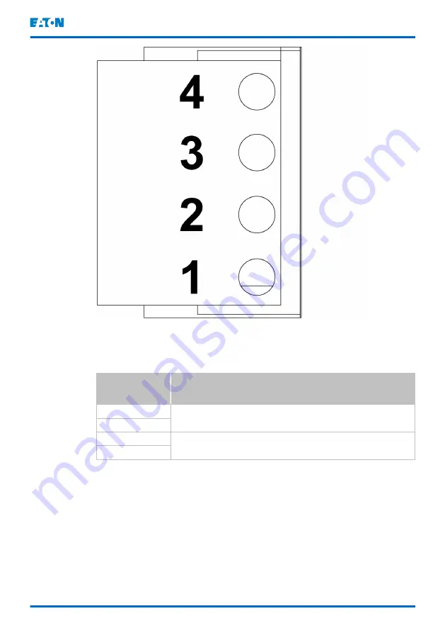
Figure 28. Remote EPO (REPO) terminal block connector assignments
Table 16: Remote EPO connections
Remote EPO
terminal
Description
1
Input: a normally-closed dry contact used to activate UPS EPO
from a remote switch.
2
3
Input: a normally-open dry contact used to activate UPS EPO
from a remote switch.
4
4.
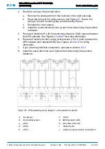
Route the remote EPO wiring to the terminal block, see Figure
.
5.
Connect the wiring as shown in Table
for a normally-open
for a normally-closed remote EPO.
6.
If you are using a normally-closed remote EPO switch, connect a jumper
wire between pins 3 and 4 on the remote EPO terminal block.
7.
If you are installing multiple remote EPO switches, wire the additional
switches in parallel with the first remote EPO.
8.
If required, install wiring from the remote EPO switch to the trip circuitry of
the upstream protective devices. A second contact block is provided on the
Eaton 93E Generation 2 UPS 100-200 kVA
(380/400/415V)
User's and installation guide
©
Eaton Corporation plc 2019. All rights reserved.
Revision: 002
Document ID: P-164000848
69 (118)


