background image

 
P-164000427 

SMALL and LARGE BATTERY CABINET 

11 

Revision 2 

User's and Installation Guide 


5. 

Select the  cable  routing  out  of different options and  route the  cables to  the  dedicated 
connectors inside  UPS  cabinet. Terminals are located under the circuit breaker and 
are marked with +, - and a protecting earth designators. 


6. 

Apply cable  glands and/or  plastic  pass-through collars  accordingly. 


WARNING


Make sure all power sources are disconnected before next steps. 


7. 

Connect  the  power  cables  and  signal  wires  to  the  UPS.  No  signal  wires  are  connected  to 
93E UPS. 

8. 

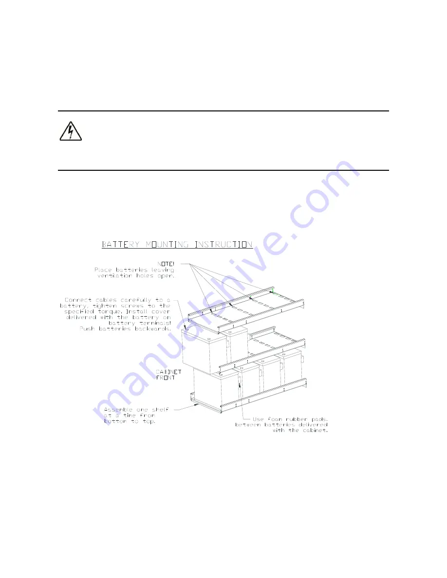
Battery installation is to be done on-site by authorized and trained service personnel. Batteries are 
to be installed on the shelves according to the following  picture. Ensure  you find a correct wiring 
instruction included into the cabinet and follow it. 


Figure  2 -4: Battery mounting on the shelves 


Summary of Contents for 93E

Page 1: ...Eaton 93P ESMALLandLARGEEXTERNALBATTERYCABINET P 164000427 User s and Installation Guide...

Page 2: ......

Page 3: ...Eaton 93P E SMALL and LARGE External Battery Cabinet User s and Installation Guide...

Page 4: ...al application in the second environment Installation restrictions or additional measures may be needed to prevent disturbances 2013 Eaton Corporation All Rights Reserved The contents of this manual a...

Page 5: ...ing the Large Battery Cabinet installation 10 2 3 Installation with other than 93PM or 93E UPS 13 3 Maintenance 14 3 1 Important safety instructions 14 3 2 Performing preventive maintenance 15 3 2 1 P...

Page 6: ...Refer to your operator s manual for additional information such as important operating and maintenance instructions Figure 1 1 Recycling batteries symbol This symbol indicates that you should not dis...

Page 7: ...hey are defined Icon Description NOTE Information notes call attention to important features or instructions 1 3 General The battery cabinet contains components that carry high currents and voltages T...

Page 8: ...strings before installation CAUTION Installation or servicing should be performed by qualified service personnel knowledgeable of batteries and required precautions Keep unauthorized personnel away fr...

Page 9: ...ritten for a global reader NOTE Read the manual before operating or working on the UPS system 1 5 CE marking The product has the CE marking in compliance with the following European directives LV Dire...

Page 10: ...ange is from 20 to 25 C WARNING Hydrogen and oxygen gases are emitted from batteries into the surrounding atmosphere during charge float charge heavy discharge and overcharge Explosive gas mixture may...

Page 11: ...n manual for UPS configuration The allowed battery block configurations for 93PM and 93E UPSs are presented in table 2 1 Table 2 1 Battery block configuration for 93PM and 93E UPSs 93PM 30 50 kW 93PM...

Page 12: ...abinet For the 80 120 kVA models the bottom cable entry is in the front section of the bottom plate and for the 160 200 kVA models the entry is in the rear section of the bottom plate NOTE Installatio...

Page 13: ...em must be installed on a level floor suitable for computer or electronic equipment The system must be installed in a temperature and humidity controlled indoor area free of conductive contaminants 2...

Page 14: ...bottom or the rear entry 4 Open the battery cabinet and locate the external power wiring shipped along the cabinet 5 Cables with single insulation are provided with the battery cabinet These cables c...

Page 15: ...inet placement but for easier service access to UPS on the 93PM 30 150 kW UPS right side is preferred and on the 93PM 160 200 kW left side is preferred The battery cabinet must be located on the right...

Page 16: ...le glands and or plastic pass through collars accordingly WARNING Make sure all power sources are disconnected before next steps 7 Connect the power cables and signal wires to the UPS No signal wires...

Page 17: ...ets are to be used repeat the steps for the rest of the cabinets and in 93PM system be sure to daisy chain the signal wire harnesses in the next cabinet 93E system does not use signal wiring Signal wi...

Page 18: ...ET 13 Revision 2 User s and Installation Guide 2 3 Installation with other than 93PM or 93E UPS Other UPSs may not be fully compatible with 93P E External Battery Cabinet Check UPS manual for the requ...

Page 19: ...only LETHAL VOLTAGE PRESENT This unit should not be operated with the cabinet doors open or protective panels removed Do not make any assumptions about the electrical state of any cabinet in the UPS s...

Page 20: ...ons Maintenance procedures should specify that the bolted connections be re torqued 3 2 2 ANNUAL maintenance Annual preventive maintenance should be performed only by authorized service personnel fami...

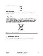
Page 21: ...ries may contain HIGH VOLTAGES and CAUSTIC TOXIC and FLAMMABLE substances Batteries can injure or kill people and damage equipment if used improperly DO NOT DISCARD unwanted batteries or battery mater...

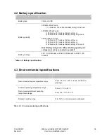
Page 22: ...epresentative Due to continuous product improvement programs specifications are subject to change without notice 4 1 Standards and regulations Safety IEC 62040 1 IEC 60950 1 Performance tests IEC 6204...

Page 23: ...locks 228 cells per battery string or 3 40 blocks 240 cells per battery string 2V per cell Note Battery strings with different battery quantity and voltage must not be connected in parallel Battery Vo...

Page 24: ...tenance of the UPS shall also be performed only by a service engineer approved by Eaton Otherwise the warranty will be voided If the product fails to meet its published specifications due to a defect...

Page 25: ...the UPS to the battery cabinet Note 93PM only Room ventilation and air conditioning equipment are installed and operating correctly The area around the installed UPS system is clean and dust free It...

Page 26: ...P 164000427 SMALL and LARGE BATTERY CABINET 21 Revision 2 User s and Installation Guide...

Reviews: