Eaton 93E UPS 15-80 kVA (380/400/415 V)
Installation and Operation Manual
© Eaton Corporation plc 2015. All rights reserved.
Revision: 001
Document ID: 614-01975-00
45 (133)
Battery voltage is computed at 2 volts per cell. Rated battery current is
computed at 2 volts per cell. The battery cabling used between the
battery and the UPS should not allow a voltage drop of more than 1% of
nominal DC voltage at rated battery current. If the conductors used for
DC input from the battery cabinets to the UPS are those provided by the
UPS manufacturer, and the UPS and battery cabinets are manufactured
by the same supplier, then it is acceptable if they do not meet the noted
minimum conductor sizes.
4.3.3
UPS system interface wiring preparation
Control wiring for features and options should be connected at the
communication interface terminal blocks located inside the UPS.
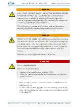
WARNING
Do not connect relay contacts directly to the mains-related circuits.
Reinforced insulation to the mains is required.
CAUTION
All the communication interfaces are SELV circuits. When connecting
to other equipment, make sure that you maintain this characteristic.
Read and understand the following notes while planning and performing
the installation:
•
Interface wiring should be rated for a minimum of 24 V, 1A.
•
For interface wiring from 30 V to 600 V, the wire should be rated for
a minimum of 600 V, 1 A.
•
Because of the remote EPO and signal input wiring route in the
UPS cabinet, the wire should be rated for a minimum of 300 V.
•
Use twisted-pair wires for each input and return or common.
•
All interface wiring and conduit is provided by the operator.
•
When installing external interface wiring between a remote EPO or
signal input and the UPS interface terminals, conduit must be
installed between each device and the UPS cabinet.

