Eaton 93E UPS 15-80 kVA (380/400/415 V)
Installation and Operation Manual
© Eaton Corporation plc 2015. All rights reserved.
Revision: 001
Document ID: 614-01975-00
68 (133)
4.
Remove the small parts from the knockout in the right side plate.
5.
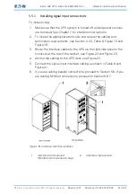
Route and install the RJ-45 Controller Area Network (CAN) cables
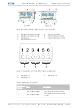
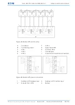
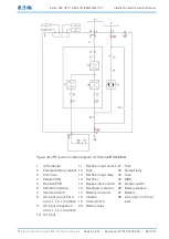
between the UPS cabinets. See Figure 20, Figure 24 and Figure 25
for wiring information.
6.
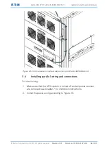
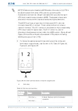
Route and install pull chain wiring (twisted wires 0.5-2.0 mm2)
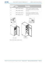
between the UPS cabinets and cabinet MOBs. See Figure 20,
Figure 24 and Figure 26 for wiring information.
7.
Anchor the cabling to the UPS door.
8.
If you are wiring MiniSlot connections, proceed to Section 5.6.1.
5.6.1
Installing MiniSlot interface connections
NOTE: The LAN drop for connection to the UPS communications card
is to be supplied by the customer.
For installation and setup of a MiniSlot card, contact an Eaton service
representative (see Section 2.7)
To install wiring:
1.
If not already installed, install the LAN drop.
2.
Route and install the LAN and other cables to the appropriate
MiniSlot cards. See Figure 19 and Figure 20 for the MiniSlot
communication bay locations.
3.
Anchor the cabling to the UPS door.
4.
Refer to the manual supplied with the MiniSlot card for operator
instructions.
5.
Install the power terminal cover using the provided hardware.
5.7
Installing a remote EPO switch
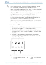
A latching-type remote Emergency Power-off (EPO) switch can be used
in an emergency to shut down the UPS and remove power to the critical
load from a location away from where the UPS is installed.

