Eaton 93E UPS 15-80 kVA (380/400/415 V)
Installation and Operation Manual
© Eaton Corporation plc 2015. All rights reserved.
Revision: 001
Document ID: 614-01975-00
117 (133)
8
Communication
This chapter describes the communication features of the Eaton 93E
UPS. For terminal wiring information, see Section 4.3.3 and Section 5.3.
For location of the communication interface panel and terminals, see
Figure 19 and Figure 20.
8.1
MiniSlot cards
The Eaton 93E UPS has 2 standard, factory-installed MiniSlot
communication bays. See Figure 20 for the bay locations. The UPS is
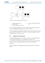
compatible with the following MiniSlot cards (see Figure 43):
•
Network Management MiniSlot card
Provides remote monitoring through a Web browser interface, e-
mail, and a network management system (NMS) using SNMP and
connects to a twisted-pair Ethernet (10/100BaseT) network.
•
Network and Modbus MiniSlot card
Provides remote monitoring through a Web browser interface, e-
mail, and a network management system (NMS) using SNMP and
connects to a twisted-pair Ethernet (10/100BaseT) network. The
card also provides direct integration of UPS information (meters and
status) to a Building Management System (BMS) using the Modbus
RTU alternative communication interface.
•
Industrial Relay Mini-Slot card
The Industrial Relay Card provides a way of connecting the Eaton
93E UPS to industrial and electrical monitoring systems. It also
enables a wide range of control applications by allowing up to 250
volts and 5 Amperes through its 5 relay connections. By connecting
wires to the corresponding places in its terminal blocks, you can
choose normally-open or normally-closed setup for each output.

