Eaton 93E UPS 15-80 kVA (380/400/415 V)
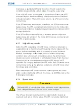
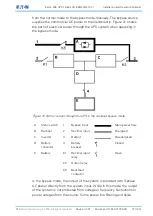
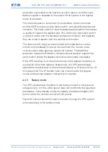
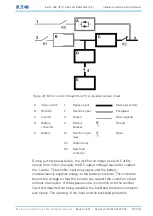
Installation and Operation Manual
© Eaton Corporation plc 2015. All rights reserved.
Revision: 001
Document ID: 614-01975-00
86 (133)
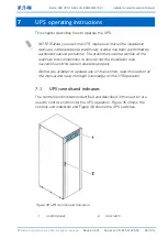
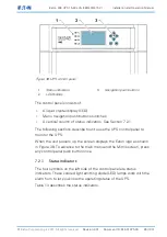
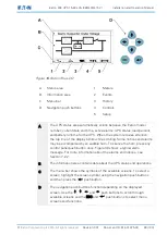
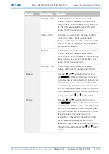
Figure 38. UPS control panel
1.
Status indicators
2.
LCD display
3.
Navigation push buttons
The control panel consists of:
•
A liquid crystal display (LCD)
•
Menu navigation push buttons switches
•
A vertical column of status indicators. See Section 7.2.1.
The following sections describe how to use the UPS control panel to
monitor the UPS.
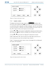
When the unit powers up, the screen displays the Eaton logo as shown
in Figure 38. To advance to the main menu and the Mimic screen, press
any control panel push button once.
7.2.1
Status indicators
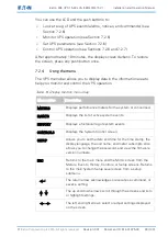
The four symbols on the left side of the control panel are status
indicators. These colored light emitting diode (LED) lamps work with the
alarm horn to let you know the operating status of the UPS.
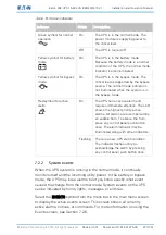
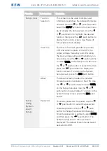
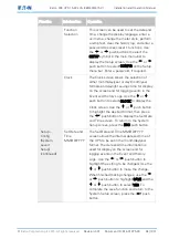
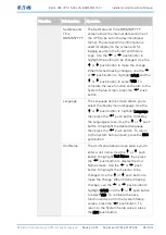
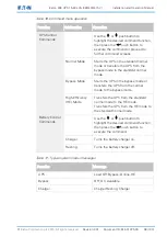
Table 13 describes the status indicators.

