1.
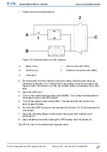
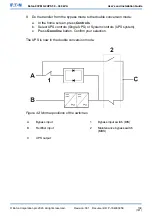
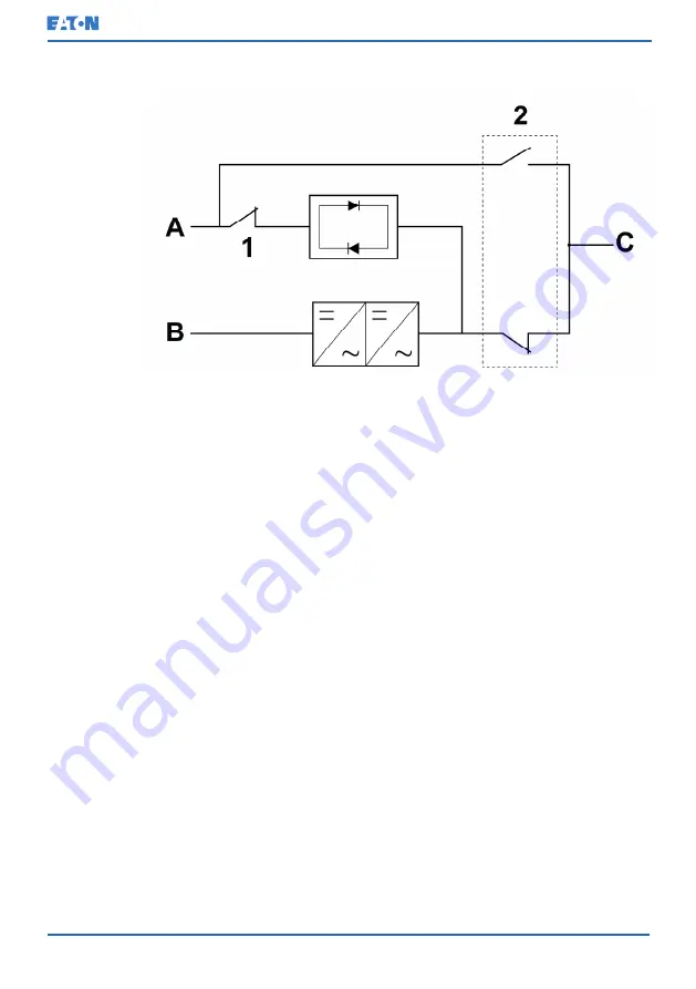
Follow the normal start position:
Figure 39: Normal positions of the switches
A
Bypass input
1
Bypass input switch (BIS)
B
Rectifier input
2
Maintenance bypass switch (MBS)
C
UPS output
2.
Do the transfer from the double conversion mode to the bypass mode as
instructed in
Section 7.4.4 Transfer from the double conversion mode to the
. Remember to verify the transfer before proceeding to the next
step.
3.
Open the UPS door.
4.
Turn on the maintenance bypass switch (MBS). This connects the feed from
the bypass input to the UPS output.
5.
Turn off the bypass input switch (BIS). This disconnects the feed for the
static bypass module.
6.
Do the LOAD OFF procedure as described in
Section 7.4.10 De-energize the
7.
Open the incoming feeder to disconnect the power from rectifier input
terminals X1.
8.
Open all battery breakers feeding the UPS battery input terminals X4.
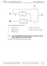
The UPS is now in the maintenance bypass mode:
© Eaton Corporation plc 2020. All rights reserved.
Revision: 001
Document ID: P-164000956
106
(141)
Eaton 93PM G2 UPS 50 – 360 kVA
User’s and Installation Guide


