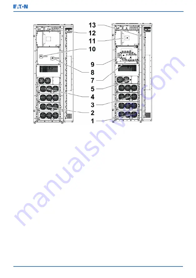
Figure 4: Main parts with MBS, inside
1. UPM 1
2. UPM 2
3. UPM 3
4. UPM 4
5. Static switch module (SSM)
6. Input fuse compartment
7. Bypass input switch (BIS) S1
8. Handle for the bypass input
switch (BIS)
9. Maintenance bypass switch
(MBS) S2
10. Handle for the maintenance
bypass switch (MBS)
11. DC-interface compartment
12. Communication interface
13. Connector area
3.3
UPS operating modes
The UPS operating modes are as follows:
© Eaton Corporation plc 2020. All rights reserved.
Revision: 001
Document ID: P-164000956
22 (141)
Eaton 93PM G2 UPS 50 – 360 kVA
User’s and Installation Guide


