48
Eaton 93PM Integrated Accessory Cabinet-Tie (50 kW and 100 kW IAC-T) Installation and Operation Manual P-164000371—Rev 05
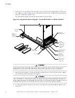
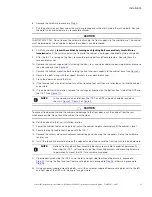
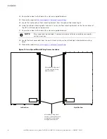
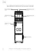
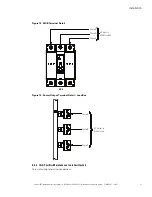
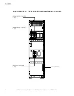
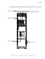
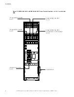
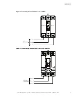
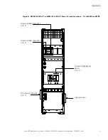
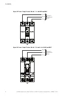
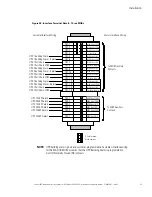
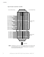
Figure 20. Power Output Terminal Detail – 3+0, 3+1, and 4+0 with MIS
2-Stud Bus Bar
Terminal
Phase A
Phase C
Phase B
AC Output to
Critical Load
MIS
44..33..33
IIA
AC
C--TT w
wiitthh aa M
Maaiinntteennaannccee IIssoollaattiioonn S
Sw
wiittcchh aanndd M
Maaiinntteennaannccee B
Byyppaassss B
Brreeaakkeerr
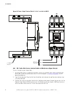
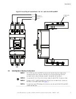
To install wiring to terminal connections
1.
Verify the UPS system is turned off and all power sources are removed. Refer to the applicable Eaton
93PM UPS Installation and Operation manual, listed in paragraph
, for UPS
operating procedures.
2.
Open the front door by lifting the latch from the bottom and turning to the right (counterclockwise) and
swing the door open.
3.
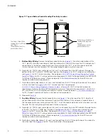
Remove the screws securing the internal safety shield panel and remove the panel to gain access to the
Module Output Breaker (MOB) input terminals, the Maintenance Bypass Breaker (MBP) input terminals,
and the Load Bus output terminals. Retain the hardware for later use.
Summary of Contents for 93PM IAC-T Series
Page 98: ...P 16400037105 P 164000371 05 ...

