Eaton 93PM Integrated Accessory Cabinet-Tie (50 kW and 100 kW IAC-T) Installation and Operation Manual P-164000371—Rev 05
39
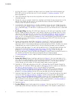
IAC-T Power Wiring Preparation
, or
for IAC-T wiring and termination
requirements. Refer to the
Eaton 93PM Integrated Accessory Cabinet-Distribution (50 kW, 100 kW, 150
kW, and 200 kW IAC-D) Installation and Operation Manual
, listed in paragraph
for IAC-D conduit and terminal locations and termination requirements.
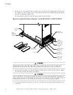
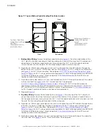
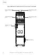
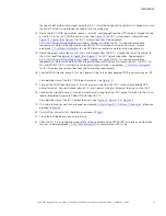
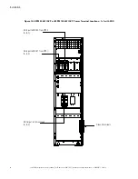
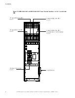
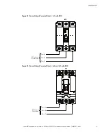
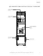
16. Connect MOB Ground, phase A, B, and C power wiring to the corresponding MOB input terminals on IAC-
T.
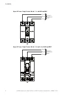
For a detailed view of the IAC-T MOB input terminals, see
.
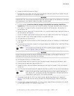
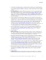
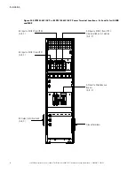
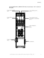
17. Connect the MOB Ground, phase A, B, and C power wiring from the IAC-T to the corresponding UPS
power terminals. Connect Ground, phase A, B, and C power wiring to the output terminals on the IAC-T.
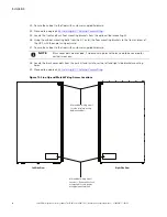
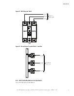
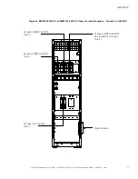
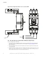
18. Connect the Ground, phase A, B, and C output power wiring from the IAC-T output terminals to the critical
load or Integrated Accessory Cabinet-Distribution (IAC-D).
For a detailed view of the IAC-T output terminals, see
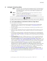
19. If wiring interface connections, proceed to paragraph
Installing IAC-T Interface Connections
; otherwise,
proceed to
.
20. Reinstall the internal safety shield panel removed in
21. Close the outside door and secure the latch.
22. After the IAC-T is installed and wired, return to the applicable Eaton 93PM UPS Installation and Operation
manual, listed in paragraph
, to complete the UPS wiring.
Summary of Contents for 93PM IAC-T Series
Page 98: ...P 16400037105 P 164000371 05 ...

