Installation
Eaton 93PM Integrated Battery Cabinet-Small Welded (IBC-SW) Installation Manual P-164000639—Rev 1
www.eaton.com/powerquality
4-3
9.
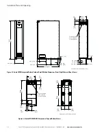
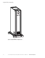
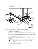
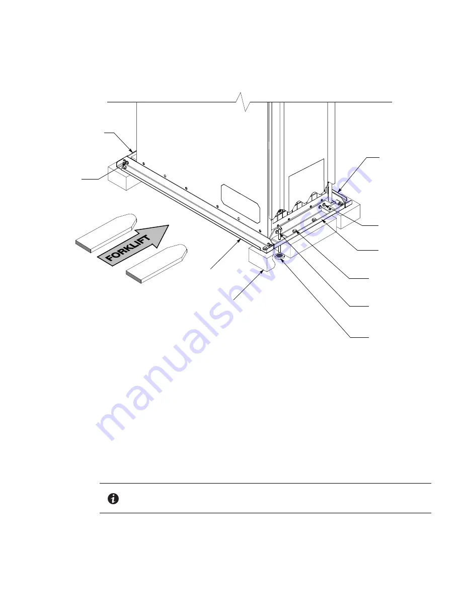
After the IBC–SW is resting on the floor, remove the jacking bolts and floor protectors. Recycle them in a
responsible manner.
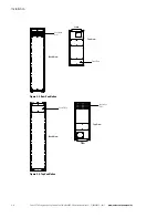
Figure 4-1. Removing the Pallet Skids and Supports – Eaton 93PM Integrated Battery Cabinet–Small Welded
10. Remove the cabinet support bolts fastening the front, rear, and side cabinet supports together and
remove the side supports (see Figure 4-1).
11. Remove the cabinet mounting bolts holding the front and rear supports to the cabinet base and remove
the supports (see Figure 4-1).
12. If installing the cabinet permanently, retain the cabinet mounting bolts; otherwise, recycle the bolts along
with the support brackets in a responsible manner.
13. Attach the front cover by placing the cover on the two mounting bolts on the bottom and installing the two
mounting bolts on the top. Tighten all of the bolts.
14. If the leveling feet are not retracted, turn all four leveling feet until they are retracted as far into the cabinet
as possible.
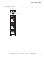
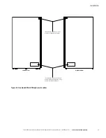
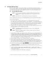
15. If line-up-and-match installation, remove the rectangular and circular knockout on the bottom and top front
side of the UPS and the IBC–SW (see Figure 4-2).
Jacking Bolt s
(2 places front)
(2 places rear)
Pallet Skid
Skid Mounting Bolts
(4 places front)
(4 places rear)
Floor Protectors
(2 places front)
(2 places rear)
Cabinet
Mounting Bolts
(4 places front)
(4 places rear)
Front Cabinet
Support
Rear Cabinet
Support
Left Side
Cabinet Support
Right Side
Cabinet Support
Cabinet
Support Bolts
(2 places at
each corner)
NOTE
The battery cabinet may be located to either the right or left of the UPS cabinet.
This procedure assumes the battery cabinet is located to the right of the UPS
cabinet.

