background image

Eaton 93PM Sidecar Integrated Accessory Cabinet-Bypass (50 kW and 100 kW SIAC-B) Installation and Operation Manual P-164000230—Rev 09

3

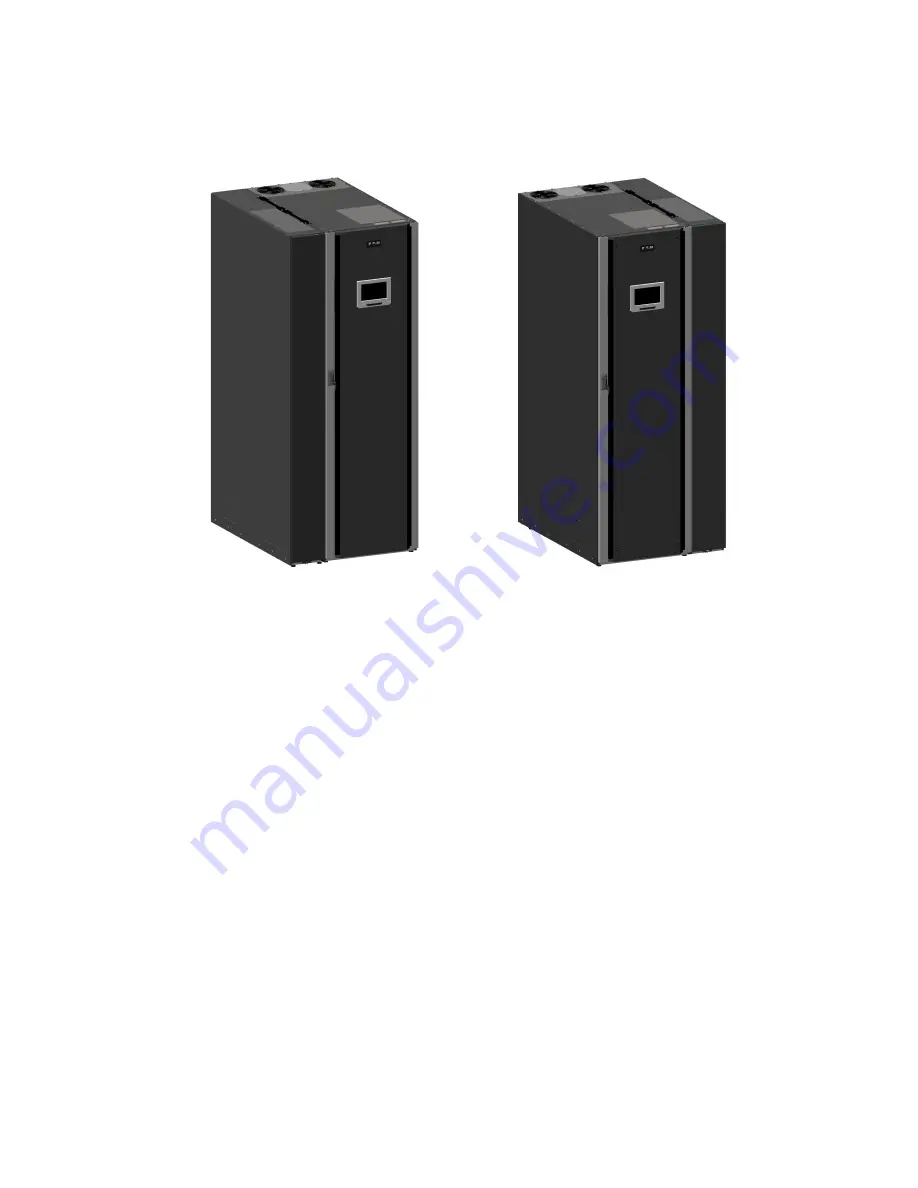
Figure 2. Eaton 93PM 100 kW SIAC-B attached to an Eaton 93PM 100 kW UPS

UPS with Left-Mounted Sidecar 


UPS with Right-Mounted Sidecar

11..44

U

Ussiinngg TThhiiss M

Maannuuaall

This manual describes how to install the SIAC-B and is divided into chapters. Read and understand the
procedures described to ensure trouble-free installation and operation.

Read through each procedure before beginning the work. Perform only those procedures that apply to the UPS
system being installed or operated.

Introduction

Summary of Contents for 93PM IBC-L

Page 1: ...164000230 Revision 09 50 kW SIAC B Three Wire 50 kW SIAC B Four Wire 100 kW SIAC B Three Wire 100 kW SIAC B Four Wire Installation and Operation Manual Eaton 93PM Sidecar Integrated Accessory Cabinet...

Page 2: ...eproduced in any way without the express written approval of Eaton IMPORTANT SAFETY INSTRUCTIONS SAVE THESE INSTRUCTIONS This manual contains important instructions that you should follow during insta...

Page 3: ...SIAC B Interface Wiring Preparation 29 3 4 Inspecting and Unpacking the SIAC B 30 4 4 I In ns st ta alllla at tiio on n 3 33 3 4 1 Preliminary Installation Information 33 4 2 Unloading the Field Inst...

Page 4: ...Installed 63 6 1 3 Transferring the UPS to Maintenance Bypass using an SIAC B 66 6 1 4 Transferring the UPS from Maintenance Bypass using an SIAC B 67 7 7 M Ma aiin nt te en na an nc ce e 6 69 9 7 1...

Page 5: ...Figure 15 Maintenance Isolation Breaker MIS Terminal Detail 40 Figure 16 Bypass Input Breaker BIB Terminal Detail 40 Figure 17 Rectifier Input Breaker RIB Terminal Detail 41 Figure 18 Typical Bus Bar...

Page 6: ...vi Eaton 93PM Sidecar Integrated Accessory Cabinet Bypass 50 kW and 100 kW SIAC B Installation and Operation Manual P 164000230 Rev 09 List of Figures...

Page 7: ...Table 5 External Power Wiring Recommendations Eaton 93PM 50 kW and 100 kW Three Wire SIAC B Two and Three Breaker Maintenance Bypass 24 Table 6 External Power Wiring Recommendations Eaton 93PM 50 kW a...

Page 8: ...viii Eaton 93PM Sidecar Integrated Accessory Cabinet Bypass 50 kW and 100 kW SIAC B Installation and Operation Manual P 164000230 Rev 09 List of Tables...

Page 9: ...Isolation MIS breaker This allows Maintenance bypass for system repair or maintenance The critical load is NOT protected in the Maintenance bypass mode Three breaker configuration used with single fee...

Page 10: ...mounted three breaker configuration containing a MBP with auxiliary contacts a MIS and a BIB Right mounted four breaker configuration containing a MBP with auxiliary contacts a MIS a BIB and a RIB Lef...

Page 11: ...nted Sidecar UPS with Right Mounted Sidecar 1 1 4 4 U Us siin ng g T Th hiis s M Ma an nu ua all This manual describes how to install the SIAC B and is divided into chapters Read and understand the pr...

Page 12: ...discard waste electrical or electronic equipment WEEE in the trash For proper disposal contact your local recycling reuse or hazardous waste center Eaton Powerware and BladeUPS are registered tradema...

Page 13: ...ing the UPS and information about maintenance and responding to system events Communication capabilities of the UPS system Refer to the Eaton 93PM UPS 20 100 kW 480V Three Wire 100 kW Frame Installati...

Page 14: ...100 kW SIAC B Installation and Operation Manual P 164000230 Rev 09 1 1 9 9 E Eq qu uiip pm me en nt t R Re eg giis st tr ra at tiio on n Please visit www eaton com pq register to register your new Eat...

Page 15: ...ants Ambient temperature must not exceed 40 C 104 F Do not operate near water or excessive humidity 95 maximum The system is not intended for outdoor use As a result of the connected loads high leakag...

Page 16: ...8 Eaton 93PM Sidecar Integrated Accessory Cabinet Bypass 50 kW and 100 kW SIAC B Installation and Operation Manual P 164000230 Rev 09 Safety Warnings...

Page 17: ...e product s resources page become void See Chapter 9 Warranty for details This service is offered as part of the sales contract for the UPS Contact an Eaton service representative in advance a minimum...

Page 18: ...SIAC B 5 Battery 1014 2235 983 2168 6 at 164 361 93PM 50 1 Redundant UPS with 4 Breaker SIAC B 0 Battery 461 1015 430 948 6 at 72 158 93PM 50 1 Redundant UPS with 4 Breaker SIAC B 3 Battery 798 1758 7...

Page 19: ...44 489 1077 6 at 82 180 93PM 100 3 Redundant UPS with Empty SIAC B Top Entry 583 1285 552 1218 6 at 92 203 Table 3 Eaton 93PM 50 kW with Left or Right Mounted Four Wire SIAC B Cabinet Weights Model We...

Page 20: ...463 1022 6 at 77 170 93PM 100 2 Redundant UPS with 4 Breaker SIAC B 558 1229 527 1162 6 at 88 194 93PM 100 3 Redundant UPS with 4 Breaker SIAC B 622 1370 591 1303 6 at 99 217 93PM 100 1 Redundant UPS...

Page 21: ...n and Operation Manual P 164000230 Rev 09 13 Figure 3 Eaton 93PM 50 kW and 100 kW UPS with SIAC B Dimensions Front View Front UPS With Left Mounted Sidecar Front UPS With Right Mounted Sidecar Dimensi...

Page 22: ...Rev 09 Figure 4 Eaton 93PM 50 kW UPS with SIAC B Dimensions Top and Bottom Views Dimensions are in millimeters Inches Top Top Bottom Bottom UPS With Left Mounted Sidecar UPS With Right Mounted Sideca...

Page 23: ...and Operation Manual P 164000230 Rev 09 15 Figure 5 Eaton 93PM 50 kW UPS with Left Mounted SIAC B Center of Gravity Dimensions are in millimeters Inches Front View Side View Sidecar can be on the left...

Page 24: ...581 22 9 401 15 8 494 1088 93PM 50 2 Redundant UPS with 4 Breaker SIAC B 3 Battery 870 34 3 559 22 0 434 17 1 831 1831 Weight and Center of Gravity with Left or Right Mounted 50 kW Three Wire Empty S...

Page 25: ...tery 958 37 7 586 23 1 390 15 3 445 982 93PM 50 2 Redundant UPS with 4 Breaker SIAC B 0 Battery 1005 39 6 580 22 8 402 15 8 509 1123 Weight and Center of Gravity with Left or Right Mounted 50 kW Empty...

Page 26: ...Rev 09 Figure 6 Eaton 93PM 100 kW UPS with SIAC B Dimensions Top and Bottom Views Dimensions are in millimeters Inches Top Top Bottom Bottom UPS With Left Mounted Sidecar UPS With Right Mounted Sideca...

Page 27: ...ty with Left or Right Mounted 100 kW Three Wire SIAC B letters A B and C map to Figure 7 A mm in B mm in C mm in Installed Weight kg lb 93PM 100 1 Capacity UPS with 4 Breaker SIAC B 855 33 7 568 22 4...

Page 28: ...01 39 4 541 21 3 427 16 8 552 1218 Weight and Center of Gravity with Left or Right Mounted 100 kW Four Wire SIAC B letters A B and C map to Figure 7 A mm in B mm in C mm in Installed Weight kg lb 93PM...

Page 29: ...le to secure the UPS with SIAC B to the facility floor Figure 8 and Figure 9 show the mounting hole locations for the brackets Figure 8 UPS with SIAC B Front and Rear Floor Mounting Bracket Mounting D...

Page 30: ...nd 100 kW SIAC B Installation and Operation Manual P 164000230 Rev 09 Figure 9 UPS with SIAC B Floor Mounting Bracket Dimensions Top View 6x M12 or 6x 1 2 BOLT FRONT AND BACK TORQUE 87 Nm 64 lb ft Dim...

Page 31: ...e 250 and local codes for proper grounding practices Phase rotation must be clockwise starting with phase A rotation A B C Per NEC Article 300 20 a all three phase conductors must be run in the same c...

Page 32: ...3 146 Minimum Conductor Size Phase A B and C Number per Phase AWG or kcmil each 3 1 3 0 1 Minimum Conductor Size Ground Number per Phase AWG or kcmil each 8 1 6 1 AC Output to Critical Load Full Load...

Page 33: ...to Critical Load Full Load Current 3 Phases 1 Ground C Maximum Amps 60 120 Minimum Conductor Size Phase A B and C Number per Phase AWG or kcmil each 4 1 2 0 1 Minimum Conductor Size Ground Number per...

Page 34: ...ral Number per Phase AWG or kcmil each 3 1 2 0 1 Minimum Conductor Size Ground Number per Phase AWG or kcmil each 8 1 6 1 Building and Inter Cabinet Ground Minimum Conductor Size Ground Number per Pha...

Page 35: ...ch 8 1 6 1 AC Output to Critical Load Full Load Current 3 Phases 1 Neutral see Note 1 Ground Minimum Conductor Size Phase A B and C and Neutral Number per Phase Minimum Conductor Size Ground Number pe...

Page 36: ...Source 2 E6 Phase A 1 6 250 31 275 5 16 Hex E7 Phase B 1 6 250 31 275 5 16 Hex E8 Phase C 1 6 250 31 275 5 16 Hex 4 Wire version only E12 Neutral 2 6 300 31 275 5 16 Hex AC Output to Critical Load E9...

Page 37: ...nter Cabinet and Load Ground TBG Ground 6 14 1 0 5 1 Nm 45 Slotted 3 3 3 3 4 4 S SI IA AC C B B I In nt te er rf fa ac ce e W Wiir riin ng g P Pr re ep pa ar ra at tiio on n Control wiring for feature...

Page 38: ...factory The integrated cabinets are shipped bolted to a metal and wood pallet see Figure 10 or Figure 11 with outer protective packaging material covering the cabinet Refer to the applicable Eaton 93...

Page 39: ...t Bypass 50 kW and 100 kW SIAC B Installation and Operation Manual P 164000230 Rev 09 31 Figure 11 Eaton 93PM 100 kW UPS with SIAC B as Shipped on Pallet UPS with Left Mounted Sidecar UPS with Right M...

Page 40: ...32 Eaton 93PM Sidecar Integrated Accessory Cabinet Bypass 50 kW and 100 kW SIAC B Installation and Operation Manual P 164000230 Rev 09 Installation Plan and Unpacking...

Page 41: ...measurement tables Use the applicable procedure from the following list for the type of installation being performed For field installation of a separately shipped SIAC B proceed to paragraph 4 2 Unlo...

Page 42: ...ng the Pallet Skids and Supports Eaton 93PM Field Installed SIAC B Cabinet Mounting Bolts 2 places front 2 places rear Skid Mounting Bolts 4 places front 4 places rear Floor Protectors 2 places front...

Page 43: ...r supported by the jacking bolts 9 After the SIAC B is resting on the floor remove the jacking bolts and floor protectors Recycle them in a responsible manner 10 Remove the shipping brace screws secur...

Page 44: ...tained hardware NOTE A rear tie strap is attached to the back of the cabinet and is used only for seismic installations 8 Locate the front tie strap shipped attached to the SIAC B see Figure 12 and re...

Page 45: ...tral harnesses and MBP interface harness packed inside the SIAC B Retain for later use NOTE When routing cable harnesses ensure the cables ends marked UPS are routed to the UPS terminals 2 Route the p...

Page 46: ...corresponding terminal number of the RIB breaker For a detailed view of the RIB breaker terminals see Figure 17 Tighten terminals to 31Nm 275 lb in torque 9 If installing a four wire SIAC B proceed to...

Page 47: ...14 Eaton 93PM 50 kW and 100 kW SIAC B Left or Right Mounted Bypass Terminal Locations InputTerminal Block Source 2 Bypass Neutral Output Neutral RIB Breaker Source 1 BIB Breaker Maintenance Bypass Bre...

Page 48: ...15 Maintenance Isolation Breaker MIS Terminal Detail PHASE C MIS 6 PHASE B MIS 4 PHASE A MIS 2 AC Input to UPS Output MIS Figure 16 Bypass Input Breaker BIB Terminal Detail PHASE A BIB 1 PHASE B BIB...

Page 49: ...To disconnect wiring 1 Verify the UPS system is turned off and all power sources are removed Refer to the applicable Eaton 93PM UPS Installation and Operation manual listed in paragraph 1 7 For More...

Page 50: ...e SIAC B after removing from the UPS cabinet to prevent the SIAC B from falling 8 Carefully slide the SIAC B away from the UPS cabinet 9 Move the cabinets to the installation area 10 Proceed to paragr...

Page 51: ...to or ry y I In ns st ta alllle ed d S SI IA AC C B B f fr ro om m t th he e P Pa alllle et t a an nd d M Me ec ch ha an niic ca all I In ns st ta alllla at tiio on n The SIAC B is attached to and dir...

Page 52: ...er through the top or bottom of the SIAC B NOTE 3 Remove the SIAC B top or bottom conduit landing plate to drill or punch conduit holes see Figure 4 1 To install wiring 1 Remove the screw securing the...

Page 53: ...iring from the utility source to the SIAC B maintenance bypass input terminals See paragraph 3 3 3 SIAC B Power Wiring Preparation Table 5 Table 6 Table 7 or Table 8 for SIAC B wiring and termination...

Page 54: ...9 Figure 19 Eaton 93PM 50 kW and 100 kW SIAC B Conduit Landing Wire Entry Locations Top View Top Entry Conduit Landing Remove plate to drill or punch conduit holes Bottom View Bottom Entry Conduit Lan...

Page 55: ...t the critical load The service representative cannot perform any installation tasks other than verifying software and operating setup parameters Service personnel may request a copy of the completed...

Page 56: ...____________________________________________________ _________________________________________________________________________ _________________________________________________________________________...

Page 57: ...sory Cabinet Bypass SIAC B for the following configurations Two breaker Maintenance Bypass with a Maintenance Isolation Breaker MIS and a Maintenance Bypass Breaker MBP Three breaker Maintenance Bypas...

Page 58: ...ual P 164000230 Rev 09 Figure 21 Three Breaker SIAC B Internal Oneline 480V 3 Phase SIAC B Output to Critical Load BIB MIS MBP Input Terminals 480V 3 Phase Input to Maintenance Bypass Output Terminals...

Page 59: ...oneline drawings in this section show the simplified internal structure of the UPS battery supply and SIAC B Oneline Drawing UPS Model Voltage System Type Input Output See Figure 23 Eaton 93PM 50 3 W...

Page 60: ...Accessory Cabinet Bypass 50 kW and 100 kW SIAC B Installation and Operation Manual P 164000230 Rev 09 Figure 23 Eaton 93PM 50 kW Three Wire UPS with 93PM 50 kW Three Wire SIAC B System Online B A C UP...

Page 61: ...ted Accessory Cabinet Bypass 50 kW and 100 kW SIAC B Installation and Operation Manual P 164000230 Rev 09 53 Figure 24 Eaton 93PM 100 kW Three Wire UPS with SIAC B System Online B A C UPM 3 UPM 2 UPM...

Page 62: ...Integrated Accessory Cabinet Bypass 50 kW and 100 kW SIAC B Installation and Operation Manual P 164000230 Rev 09 Figure 25 Eaton 93PM 50 kW Four Wire UPS with SIAC B System Online B A C UPM 2 UPM 1 On...

Page 63: ...ated Accessory Cabinet Bypass 50 kW and 100 kW SIAC B Installation and Operation Manual P 164000230 Rev 09 55 Figure 26 Eaton 93PM 100 kW Four Wire UPS with SIAC B System Online UPM 3 UPM 2 UPM 1 B A...

Page 64: ...Wire SIAC B Two Breaker Schematic 2 Breaker Version E8 E6 E7 G G G G FROM BUILDING GROUND TO LOAD GROUND TO UPS GROUND FROM UPS OUTPUT 480V 3 TBG G 2 1 3 TBCTRL GND 5 4 6 MBP MAINTENANCE BYPASS BREAK...

Page 65: ...F EATON CORPORATION AND IS MERELY ON LOAN AND SUBJECT TO RECALL BY EATON AT ANY TIME BY TAKING POSSESSION OF THIS DOCUMENT THE RECIPIENT ACKNOWLEDGES AND AGREES THAT THIS DOCUMENT CANNOT BE USED IN AN...

Page 66: ...4 6 RIB RECTIFIER INPUT BREAKER BIB BYPASS INPUT BREAKER MBP MAINTENANCE BYPASS BREAKER MIS MAINTENANCE ISOLATION BREAKER A B C E11 E9 E10 A B C A B C A B C A B C A B C FROM UPS OUTPUT 480V 3 AC INPUT...

Page 67: ...100kW BYPASS SIDECAR 480V 4 WIRE 2 Breaker Version E8 E6 E7 G G G G FROM BUILDING GROUND TO LOAD GROUND TO UPS GROUND FROM UPS OUTPUT 480V 3 TBG G 2 1 3 TBCTRL LEGEND FACTORY WIRING 105 C Insulation C...

Page 68: ...ATION CONTAINED THEREON IS CONFIDENTIAL AND IS THE EXCLUSIVE PROPERTY OF EATON CORPORATION AND IS MERELY ON LOAN AND SUBJECT TO RECALL BY EATON AT ANY TIME BY TAKING POSSESSION OF THIS DOCUMENT THE RE...

Page 69: ...Insulation GND 5 4 6 RIB RECTIFIER INPUT BREAKER BIB BYPASS INPUT BREAKER MBP MAINTENANCE BYPASS BREAKER MIS MAINTENANCE ISOLATION BREAKER A B C E11 E9 E10 A B C A B C A B C A B C A B C FROM UPS OUTPU...

Page 70: ...62 Eaton 93PM Sidecar Integrated Accessory Cabinet Bypass 50 kW and 100 kW SIAC B Installation and Operation Manual P 164000230 Rev 09 Onelines and Schematics...

Page 71: ...ker MIS isolates the UPS from the bypass feed and the load Bypass Input Breaker Optional only three and four breaker configurations The Bypass Input Breaker BIB provides a single point of input power...

Page 72: ...164000230 Rev 09 7 Reinstall the SIAC B front panel and secure with retained screw Figure 33 Eaton 93PM 50 kW Three Wire SIAC B Breakers Right Mounted SIAC B UPS SIAC B NOTE The 50kW UPS is Shown RIB...

Page 73: ...llation and Operation Manual P 164000230 Rev 09 65 Figure 34 Eaton 93PM 100 kW Four Wire SIAC B Breakers Left Mounted SIAC B SIAC B UPS NOTE The 100kW UPS is Shown RIB BREAKER SOURCE 1 BIB BREAKER MAI...

Page 74: ...t at the top of the cabinet Retain screw for later use 2 Transfer the UPS from normal mode to bypass mode Refer to the applicable Eaton 93PM UPS Installation and Operation manual listed in paragraph 1...

Page 75: ...ve it from the panel hanger bracket at the top of the cabinet Retain screw for later use 2 If installed close the BIB 3 If installed close the RIB 4 Start the UPS in bypass mode Refer to the applicabl...

Page 76: ...68 Eaton 93PM Sidecar Integrated Accessory Cabinet Bypass 50 kW and 100 kW SIAC B Installation and Operation Manual P 164000230 Rev 09 SIAC B Operating Instructions...

Page 77: ...rf fo or rm miin ng g P Pr re ev ve en nt tiiv ve e M Ma aiin nt te en na an nc ce e The UPS system requires very little preventive maintenance However the system should be inspected periodically to v...

Page 78: ...na an nc ce e T Tr ra aiin niin ng g A basic training course available from Eaton gives you a competent working knowledge of the UPS system operation and teaches you how to perform first level correct...

Page 79: ...PS Eaton 93PM 50 kW Four Wire SIAC B SIAC B for the Eaton 93PM 50 kW Four Wire Capacity UPS SIAC B for the Eaton 93PM 40 kW Emergency Lighting UPS Eaton 93PM 100 kW Three Wire SIAC B SIAC B for the Ea...

Page 80: ...emperature 5 to 40 C 41 to 104 F without derating The recommended operating temperature is 25 C 77 F Storage Temperature 25 to 55 C 13 to 131 F Operating Altitude Maximum 1500m 5000 ft at 40 C without...

Page 81: ...arranty please click on the link or copy the address to download from the Eaton website UPS Product Warranty https www eaton com content dam eaton products backup power ups surge it power distribution...

Page 82: ...P 16400023009 P 164000230 09...

Reviews: