Eaton 93PM Universal Integrated Battery Cabinet (IBC-LW and IBC-LHW) Installation Manual P-164000541—Rev 04
37
9.
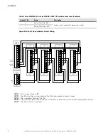
Route the other end of the battery wiring (positive, negative, and ground) to the UPS cabinet external
battery ground and input terminals. Refer to the applicable Eaton 93PM UPS Installation and Operation
manual listed in paragraph
, for UPS cabinet terminal locations and termination
requirements.
10. Connect the ground, positive, and negative power wiring to the UPS cabinet external battery ground and
input terminals.
NOTE
Route the battery wiring between the UPS and subsequent IBCs through the bottom of
the adjacent IBC.
11. Reinstall the DC power terminal shield removed in
.
12. If installing more than one IBC, repeat Steps
through
for each IBC, and then proceed to
paragraph
Battery Breaker Instantaneous Trip Setting
; otherwise, skip to paragraph
Battery Breaker Instantaneous Trip Setting
.
NOTE
Internal battery strings are to be connected by an authorized Eaton Customer Service
Engineer at system startup.
Summary of Contents for 93PM IBC-LW
Page 4: ......
Page 78: ...P 16400054104 P 164000541 04...


