50
Eaton 93PM Universal Integrated Battery Cabinet (IBC-LW and IBC-LHW) Installation Manual P-164000541—Rev 04
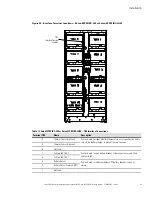
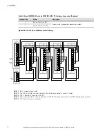
Table 12. Eaton 93PM IBC-LW or Eaton 93PM IBC-LHW – TB2 Interface Connections (Continued)
Terminal TB2
Name
Description
2
Battery Shunt Trip - (UPS)
Contacts used to open battery breaker or disconnect.
1
Battery Shunt Trip + (UPS)
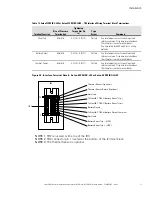
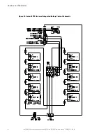
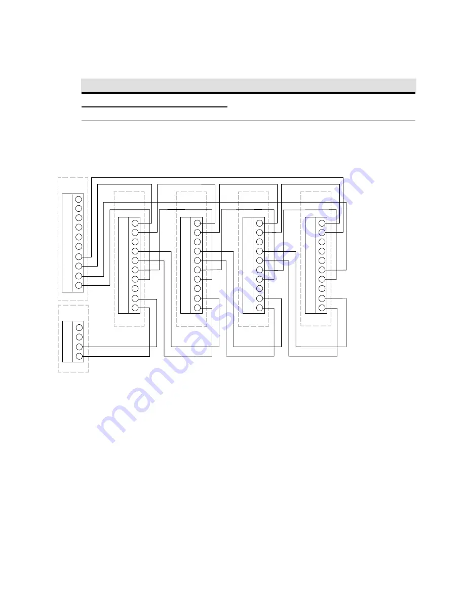
Figure 24. Shunt Trip and Battery Detect Wiring
UPS
Shunt
Trip TB
1
2
3
4
IBC1
1
2
3
4
5
6
7
8
9
10
IBC2
TB2
1
2
3
4
5
6
7
8
9
10
IBC3
1
2
3
4
5
6
7
8
9
10
IBC4
1
2
3
4
5
6
7
8
9
10
UPS
Building
Alarm TB
5
6
7
8
1
2
3
4
9
10
Shunt
Trip
Battery
Detect
Thermal
Sensor
TB2
TB2
TB2
NOTE 1
IBC1 is closest to the UPS.
NOTE 2
The IBC shunt trip is wired in parallel. The IBC battery detect is wired in series.
NOTE 3
TB2 is located at the top of the IBC.
NOTE 4
If less than four IBCs are installed, the last IBC TB2-5 connection returns to UPS Building Alarm terminal.
NOTE 5
The Thermal Sensor is optional.
Summary of Contents for 93PM IBC-LW
Page 4: ......
Page 78: ...P 16400054104 P 164000541 04...


