Eaton 93PM Universal Integrated Battery Cabinet (IBC-LW and IBC-LHW) Installation Manual P-164000541—Rev 04
53
8.
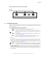
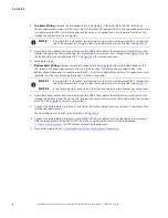
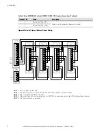
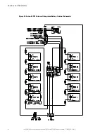
Route the battery shunt trip interface wiring from the UPS battery shunt trip interface terminals through
the bottom of the IBC to the IBC battery interface terminal block TB2. See
for terminal locations.
9.
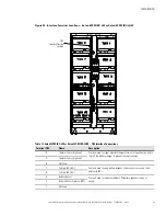
Connect the battery shunt trip interface wiring to the IBC battery shunt trip interface terminals. See
for termination requirements.
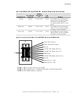
For a detailed view of the IBC terminal block, see
.
10. Connect the battery shunt trip interface wiring to the UPS battery shunt trip interface terminals. Refer to
the applicable Eaton 93PM UPS Installation and Operation manual listed in paragraph
, for UPS cabinet termination requirements.
NOTE
In the following step, if the safety shield cannot be reinstalled because of misalignment,
use the leveling feet to realign the cabinet.
11. Reinstall the internal safety shield panel removed in
of paragraph
Line-Up-and-Match Power Wiring
.
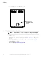
12. Install the front door (previously removed) by carefully lowering the door onto the bottom screws. Secure
the top of the door with the four retained screws and tighten the bottom screws (see
).
13. Once the battery cabinets are installed and wired, return to the applicable Eaton 93PM UPS Installation and
Operation manual, listed in paragraph
, to complete the UPS wiring.
44..55..33
IInnssttaalllliinngg TThheerrm
maall S
Seennssoorr IInntteerrffaaccee C
Coonnnneeccttiioonnss
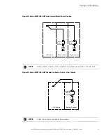
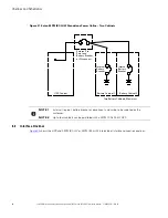
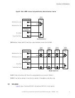
NOTE 1
The UPS thermal sensor signal uses an UPS building alarm input to indicate a thermal
trip condition and to turn off the battery charger.
NOTE 2
Any pair of unused building alarm terminals may be used for the thermal sensor
connections.
NOTE 3
Program the thermal sensor building alarm to read battery thermal trip and for normally
closed contacts.
NOTE 4
Disconnect terminal block plug from terminal block to wire plug.
NOTE 5
If the inter-cabinet wiring access pass-through is not used to install the thermal sensor
interface wiring connections, conduit must be installed between the battery cabinet and
the UPS cabinet.
NOTE 6
See paragraph
IBC Interface Wiring Preparation
, and
for wiring
and termination requirements.
NOTE 7
Refer to the applicable Eaton 93PM UPS Installation and Operation manual listed in
paragraph
, for UPS cabinet terminal locations.
To install wiring:
1.
If not already removed, remove the front door by loosening the left and right side bottom screws and
removing four top screws (see
) from the door. Lift the door to disengage the door from the
bottom screws. Retain the hardware for later use.
2.
If not already removed, remove the screws securing the internal safety shield panel (dead front) and
remove the panel to gain access to the battery power terminals. Retain the hardware for later use.
3.
If wiring the IBC thermal sensor interface terminals using line-up-and-match wiring using the inter-cabinet
wiring access pass-through (see
) proceed to
; if wiring the IBC thermal sensor interface
terminals using the top entry access, proceed to
; if wiring the IBC thermal sensor interface
terminals using the bottom entry access, proceed to
.
Summary of Contents for 93PM IBC-LW
Page 4: ......
Page 78: ...P 16400054104 P 164000541 04...


