Eaton 93PM Universal Integrated Battery Cabinet (IBC-LW and IBC-LHW) Installation Manual P-164000541—Rev 04
61
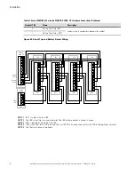
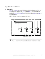
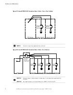
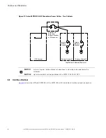
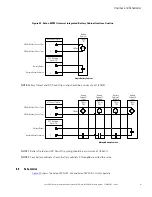
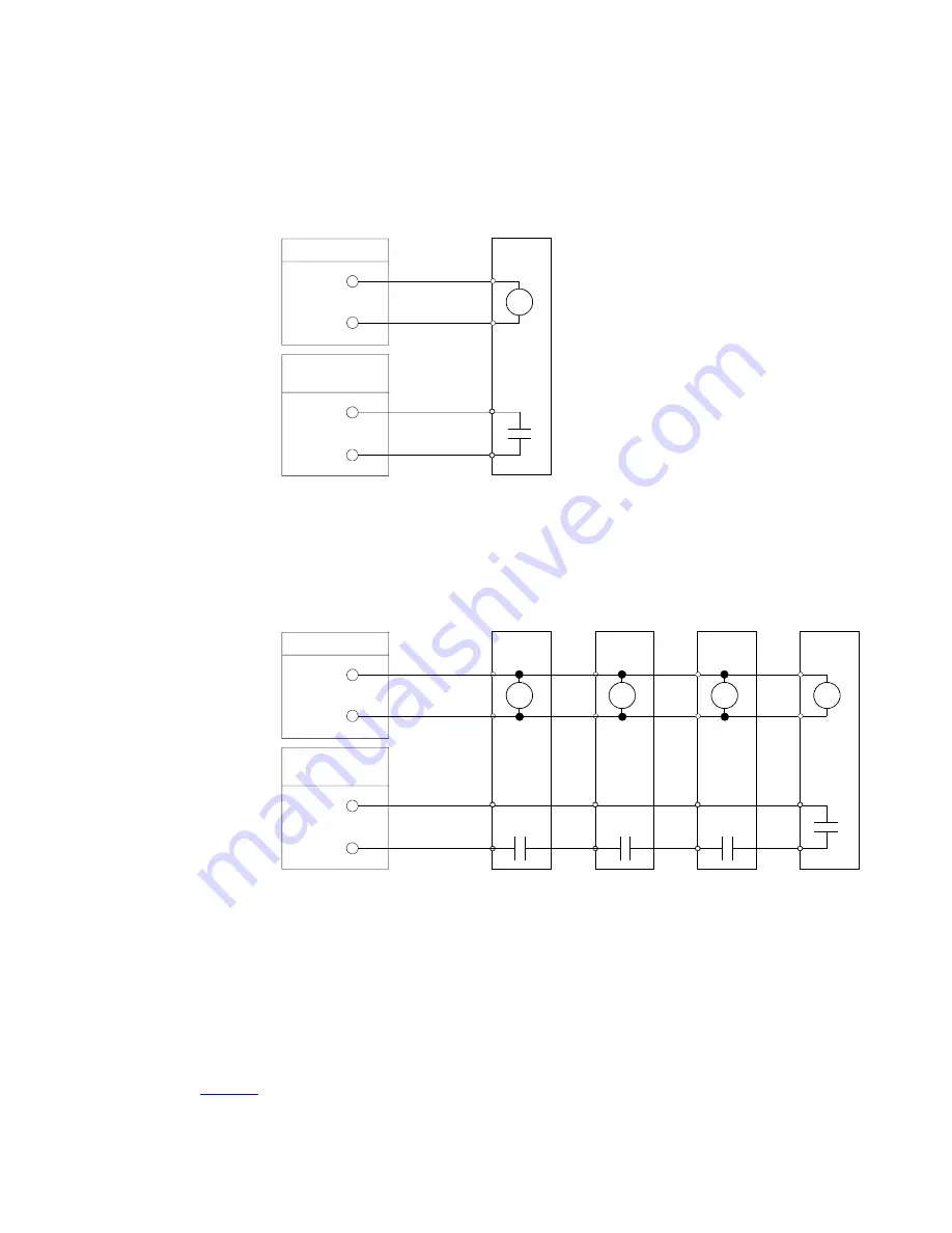
Figure 32. Eaton 93PM Universal Integrated Battery Cabinet Interface Oneline
Battery
Cabinet 1
(First)
ST
Battery
Cabinet 2
(Middle)
ST
Battery
Cabinet 4
(Last)
ST
Battery
Cabinet 3
(Middle)
ST
Multiple Battery Cabinets
48 Vdc
UPS Shunt Trip TB
Battery
Cabinet
ST
Single Battery Cabinet
Battery Detect
Battery Detect Common
48 Vdc Battery Shunt Trip +
48 Vdc Battery Shunt Trip –
1
2
48 Vdc
TB2 or
TB3
TB2 or
TB3
TB2 or
TB3
TB2 or
TB3
UPS Building
Alarm TB
1
2
TB2 or
TB3
UPS Shunt Trip TB
Battery Detect
Battery Detect Common
48 Vdc Battery Shunt Trip +
48 Vdc Battery Shunt Trip –
1
2
UPS Building
Alarm TB
1
2
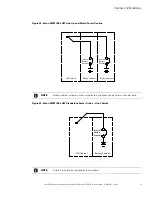
NOTE
Battery Detect and DC Shunt Trip wiring should be a minimum of 18 AWG.
NOTE 1
Battery Detect and DC Shunt Trip wiring should be a minimum of 18 AWG.
NOTE 2
Four battery cabinets shown. Battery cabinets 5 through8 are wired the same.
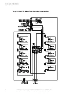
55..33
S
Scchheem
maattiiccss
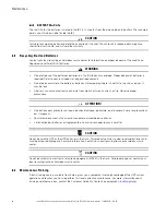
shows the Eaton 93PM IBC-LW and Eaton 93PM IBC-LHW schematic.
Summary of Contents for 93PM IBC-LW
Page 4: ......
Page 78: ...P 16400054104 P 164000541 04...

