44
Eaton 93PM Universal Integrated Battery Cabinet (IBC-LW and IBC-LHW) Installation Manual P-164000541—Rev 04
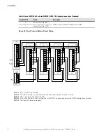
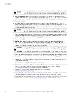
15. Route the battery wiring (positive, negative, and ground) from the UPS DC Input terminals or DC
disconnect tie point through the top of the IBC and the IBC inter-cabinet wiring access pass-through
running the cables behind the Battery Breaker assembly to the IBC DC Output and ground terminal blocks.
See
, or
for terminal locations.
16. Connect the ground wiring to the ground terminal on the IBC. Connect the positive and negative power
wiring to the IBC DC (+) and DC (–) output terminals on the IBC.
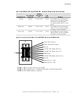
For a detailed view of the IBC terminal block, see
17. Connect the ground, positive, and negative DC power wiring from the IBC or disconnect to the UPS
cabinet ground and battery terminals.
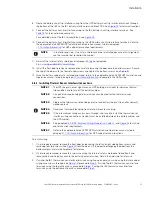
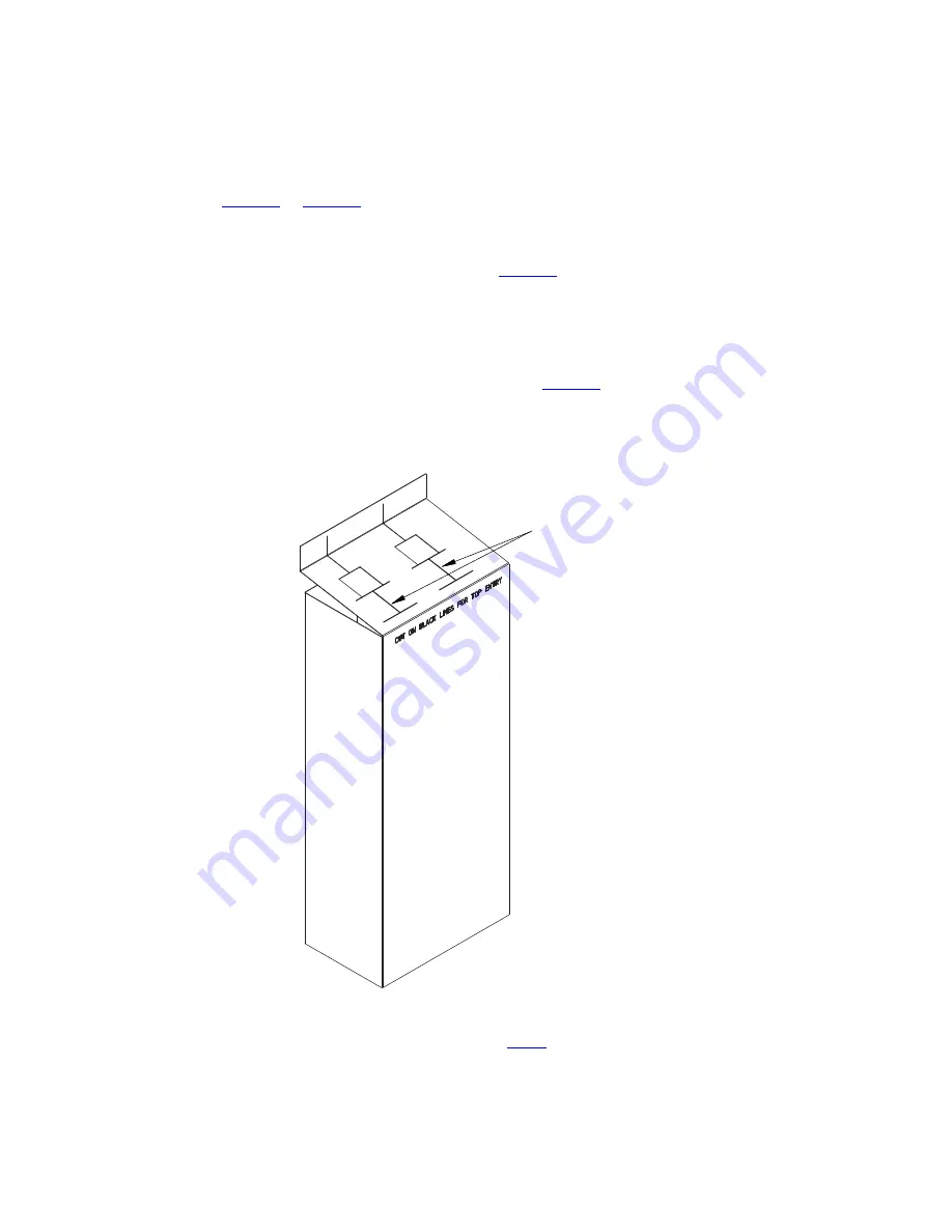
18. Take the DC power terminal shield and carefully cut along the indicated lines on the top flap. These slots
provide the extra space for the top wiring.
For a detailed view of the DC power terminal shield, see
Figure 19. DC Power Terminal Shield
Cut Lines for Top Entry Wiring
19. Reinstall the DC power terminal shield removed in
Summary of Contents for 93PM IBC-LW
Page 4: ......
Page 78: ...P 16400054104 P 164000541 04...


