Eaton 93PM-L 20–200kW (208V) UPS Installation and Operation Manual 164000724—Rev 01
3
11..11..22
C
Coonnttrrooll P
Paanneell
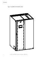
The control panel, located on the front of the UPS, contains a color liquid crystal touch screen display (LCD) and
a horizontal row of LED indicators to control the operation of the UPS and to display the status of the UPS
system. See
for additional information.
11..11..33
C
Cuussttoom
meerr IInntteerrffaaccee
•
Building Alarm Monitoring
– Up to five inputs in the UPS are available to connect the facility's alarm
system contacts. Some system configurations may limit the number of inputs available. The UPS uses
these inputs to monitor the building alarms in addition to the UPS status. See
for additional information.
•
Alarm Contact
– One alarm contact is provided for connection to equipment at the facility, such as a light,
an audible alarm, or a computer terminal. The equipment connected to this contact alerts you to a UPS
alarm. See
, for additional information.
•
Minislot Communication Bays
– Four communication bays are standard equipment. One to four optional
Minislot® connectivity cards can be installed in the UPS at any time. Minislot cards are quickly installed at
the front of the UPS and are hot-pluggable. See
, for additional information.
11..11..44
EEnneerrggyy S
Saavveerr S
Syysstteem
m M
Mooddee
The 93PM-L Series UPS offers an Energy Saver System (ESS) mode that maximizes efficiency by eliminating
unnecessary power conversion when the commercial power source is within acceptable voltage and frequency
limits. In this mode, the UPS is actively monitoring the critical bus and instantly and seamlessly transitions to
double-conversion mode (inverter online) if a commercial electrical power brownout, blackout, overvoltage,
undervoltage, or out-of-tolerance frequency condition occurs. See , for additional information.
11..11..55
IInntteerrnnaall R
Reedduunnddaannccyy
To deliver greater reliability, the Eaton 93PM-L UPS can be configured for internal redundancy. When
configured, the UPS automatically becomes redundant if the load is at or below the capacity of the UPMs
minus the capacity of one UPM. Under normal conditions the UPMs in the UPS share the load equally. If one or
more UPMs becomes unavailable and the load is at or below the capacity of remaining UPMs, the remaining
UPMs supply the load instead of transferring to bypass.
11..11..66
A
Addvvaanncceedd B
Baatttteerryy M
Maannaaggeem
meenntt
Advanced Battery Management (ABM) technology uses sophisticated sensing circuitry and a three-stage
charger. The charger is a high-frequency, IGBT-based power conversion stage that extends the useful service
life of UPS batteries by isolating the battery from the electrical environment, except for periodic charging or
reserve mode operation. ABM also protects batteries from damage due to high current charging and inverter
ripple currents. Charging at high currents can overheat and damage batteries.
ABM extends battery life by keeping the batteries charged and performing periodic battery testing. The battery
test checks the batteries by transferring to battery mode. During the test the battery voltage is constantly
monitored to determine Battery Health
.
ABM is intended for VRLA style batteries.
An ABM charging cycle starts with the charger driving the battery voltage at maximum current limit, to a
battery charge level of 2.30volts/cell. The time it takes for the voltage to reach to the battery charge level is
saved as the battery charge time. If the battery charge time exceeds 24 hours, an alarm sounds.
When the battery reaches the float level, the battery is charged at the float level for 48 hours. Due to charger
capability, some battery cabinet configurations extend float level to 72 hours. Twenty-four hours into the float
period, a series of battery tests are performed to check the battery health. The float level charge continues
after a successful test.
After initial startup, the battery run time on the front panel display indicates two minutes. After the 24-hour float
charging period and automated battery testing, the actual battery run time is determined and the actual battery
run time is displayed.
Summary of Contents for 93PM-L IAC-B
Page 162: ...16400072401 164000724 01 ...


