background image

Eaton 93PM 50-100 kW SIAC-T and 50-100 kW SIAC-TB Installation and Operation Manual P-164000370—Rev 04

33

C

Chhaapptteerr 44 IInnssttaallllaattiioonn

This chapter includes installation instructions for the Sidecar Integrated Accessory Cabinet-Tie (SIAC-T) and
Sidecar Integrated Accessory Cabinet-Tie Bypass (SIAC-TB).

NOTE

The SIAC-T or SIAC-TB is attached to and directly integrated with one of the UPS
cabinets at the factory for use in a two UPS parallel system. This section must be used
along with the applicable Eaton 93PM UPS Installation and Operation manual listed in
paragraph

1.7

For More Information

during installation.

44..11

P

Prreelliim

miinnaarryy IInnssttaallllaattiioonn IInnffoorrm

maattiioonn

WARNING

Installation should be performed only by qualified personnel.

Refer to the following while installing the SIAC-T or SIAC-TB:

Chapter 3

Installation Plan and Unpacking

for cabinet dimensions, equipment weight, wiring and terminal

data, and installation notes.

Do not tilt the cabinets more than ±10° during installation. See

Figure 6

for SIAC-T center of gravity

measurements or

Figure 9

for the SIAC-TB center of gravity measurements.

44..22

U

Unnllooaaddiinngg tthhee S

SIIA

AC

C--TT oorr S

SIIA

AC

C--TTB

B ffrroom

m tthhee P

Paalllleett aanndd M

Meecchhaanniiccaall IInnssttaallllaattiioonn

The SIAC-T or SIAC-TB is attached to and directly integrated with one of the UPS cabinets at the factory for use
in a two UPS parallel system. Refer to the applicable Eaton 93PM UPS Installation and Operation manual listed
in paragraph

1.7

For More Information

for unloading and mechanical installation instructions.

NOTE

The SIAC-T or SIAC-TB is attached to and directly integrated with one of the UPS
cabinets at the factory for use in a two UPS parallel system. The SIAC-T and SIAC-TB are
designed to be located between two UPS in a line-up-and-match configuration. This
section must be used along with the applicable Eaton 93PM UPS Installation and
Operation manual listed in paragraph

1.7

For More Information

during installation.

After completing the unloading and installation of the UPS with the attached SIAC-T or SIAC-TB, use the same
instructions to unload the second UPS and install adjacent to the SIAC-T or SIAC-TB.

44..33

IInnssttaalllliinngg tthhee S

SIIA

AC

C--TT oorr S

SIIA

AC

C--TTB

B P

Prreew

wiirreedd C

Caabblleess

NOTE 1

The SIAC-T or SIAC-TB Module Output Breaker (MOB) phase wiring is prewired
between the attached UPS and the SIAC-T or SIAC-TB.

NOTE 2

The SIAC-T or SIAC-TB MOB phase wiring for the second UPS is prewired to the MOB
and is coiled inside the sidecar.

To install wiring:

1.

Verify the UPS system is turned off and all power sources are removed. Refer to the applicable Eaton
93PM UPS Installation and Operation manual listed in paragraph

1.7

For More Information

, for UPS

operating procedures.

2.

Remove the screw securing the bottom of the SIAC-T or SIAC-TB front panel. Lift the panel straight up to
remove it from the panel hanger bracket at the top of the cabinet. Retain screw for later reuse.

Summary of Contents for 93PM SIAC-T

Page 1: ...p n P 164000370 Revision 04 50 kW SIAC T 50 kW SIAC TB 100 kW SIAC T 100 kW SIAC TB Installation and Operation Manual Eaton 93PM Sidecar Integrated Accessory Cabinet Tie and Tie Bypass ...

Page 2: ...roduced in any way without the express written approval of Eaton IMPORTANT SAFETY INSTRUCTIONS SAVE THESE INSTRUCTIONS This manual contains important instructions that you should follow during installation and maintenance of the UPS and batteries Please read all instructions before operating the equipment and save this manual for future reference CONSIGNES DE SÉCURITÉ IMPORTANTES CONSERVER CES INS...

Page 3: ...2 4 SIAC T and SIAC TB Interface Wiring Preparation 27 3 3 Inspecting and Unpacking the SIAC T or SIAC TB 28 4 4 I In ns st ta alllla at tiio on n 3 33 3 4 1 Preliminary Installation Information 33 4 2 Unloading the SIAC T or SIAC TB from the Pallet and Mechanical Installation 33 4 3 Installing the SIAC T or SIAC TB Prewired Cables 33 4 4 Installing SIAC T External Power Wiring 35 4 5 Installing S...

Page 4: ... using an SIAC TB 76 7 7 M Ma aiin nt te en na an nc ce e 7 77 7 7 1 Important Safety Instructions 77 7 2 Performing Preventive Maintenance 77 7 2 1 DAILY Maintenance 77 7 2 2 PERIODIC Maintenance 77 7 2 3 ANNUAL Maintenance 77 7 3 Maintenance Training 78 8 8 P Pr ro od du uc ct t S Sp pe ec ciif fiic ca at tiio on ns s 7 79 9 8 1 Model Numbers 79 8 2 Specifications 79 8 2 1 Input 79 8 2 2 Output ...

Page 5: ...S as Shipped on Pallet 31 Figure 14 Line Up and Match Wiring Access Locations 34 Figure 15 93PM 50 kW SIAC T 93PM 50 kW SIAC TB and 93PM 100 kW SIAC T Conduit Landing Wire Entry Locations 36 Figure 16 93PM 50 kW SIAC T and 93PM 100 kW SIAC T Output Power and Ground Terminal Locations 37 Figure 17 93PM 50 kW SIAC T and 93PM 100 kW SIAC T with MIS Output Power Terminal Detail 38 Figure 18 93PM 50 kW...

Page 6: ... with MIS 65 Figure 38 Eaton 93PM 50 kW or 100 kW UPS with Eaton 93PM 50 kW or 100 kW SIAC TB System Online 66 Figure 39 Eaton 93PM 50 kW SIAC T and 93PM 100 kW SIAC T Two Breaker without MIS Schematic 67 Figure 40 Eaton 93PM 50 kW SIAC T and 93PM 100 kW SIAC T Three Breaker with MIS Schematic 68 Figure 41 Eaton 93PM 50 kW SIAC TB and 93PM 100 kW SIAC TB Schematic 69 Figure 42 93PM 50 kW SIAC T or...

Page 7: ...e Bypass 24 Table 6 External Power Wiring Recommendations for the Eaton 93PM 50 kW SIAC TB and 93PM 100 kW SIAC TB 2 0 Parallel Configuration with Maintenance Bypass 25 Table 7 External Input Power Cable Terminations for the Eaton 93PM 50 kW SIAC T 1 1 and 2 0 Parallel Configurations 26 Table 8 External Input Power Cable Terminations for the Eaton 93PM 50 kW SIAC TB 1 1 and 2 0 Parallel Configurat...

Page 8: ...viii Eaton 93PM 50 100 kW SIAC T and 50 100 kW SIAC TB Installation and Operation Manual P 164000370 Rev 04 List of Tables ...

Page 9: ...s to be paralleled together for increased capacity or redundant capability Maintenance Bypass MBP and Maintenance Isolation MIS breakers enable power to completely bypass the UPSs externally allowing the UPSs to be safely serviced or replaced without interrupting power to critical systems Figure 1 shows the 50 kW SIAC T or 50 kW SIAC TB mounted to the 50 kW UPS cabinet Figure 2 shows the 100 kW SI...

Page 10: ...mounted configuration containing two MOBs with auxiliary contacts and a MIS breaker Left mounted configuration containing two MOBs with auxiliary contacts Left mounted configuration containing two MOBs with auxiliary contacts and a MIS breaker 93PM 100 kW SIAC TB Right mounted configuration containing two MOBs with auxiliary contacts a MBP breaker with auxiliary contacts and a MIS breaker Left mou...

Page 11: ...SIAC T and 50 100 kW SIAC TB Installation and Operation Manual P 164000370 Rev 04 3 Figure 2 93PM 100 kW SIAC T attached to an Eaton 93PM 100 kW UPS UPS with Left Mounted UPS with Right Mounted Sidecar Sidecar Introduction ...

Page 12: ...ure trouble free installation and operation Read through each procedure before beginning the procedure Perform only those procedures that apply to the UPS system being installed or operated 1 1 5 5 C Co on nv ve en nt tiio on ns s U Us se ed d iin n T Th hiis s M Ma an nu ua all This manual uses these type conventions Bold type highlights important concepts in discussions key terms in procedures a...

Page 13: ... operating and maintenance instructions Special Symbols The following are examples of symbols used on the UPS or accessories to alert you to important information RISK OF ELECTRIC SHOCK Observe the warning associated with the risk of electric shock symbol CAUTION REFER TO OPERATOR S MANUAL Refer to your operator s manual for additional information such as important operating and maintenance instru...

Page 14: ...lity or contact an Eaton service representative for information on how to obtain copies of these manuals 1 1 8 8 G Ge et tt tiin ng g H He ellp p If help is needed with any of the following Scheduling initial startup Regional locations and telephone numbers A technical question about any of the information in this manual A question this manual does not answer Please call the Customer Reliability C...

Page 15: ...nt temperature must not exceed 40 C 104 F Do not operate near water or excessive humidity 95 maximum The system is not intended for outdoor use As a result of the connected loads high leakage current is possible Connection to earth ground is required for safety and proper product operation Do not check UPS system operation by any action that includes removal of the earth ground connection with loa...

Page 16: ...8 Eaton 93PM 50 100 kW SIAC T and 50 100 kW SIAC TB Installation and Operation Manual P 164000370 Rev 04 Safety Warnings ...

Page 17: ...his service is offered as part of the sales contract for the UPS Contact an Eaton service representative in advance a minimum two week notice is required to reserve a preferred startup date 3 3 1 1 C Cr re ea at tiin ng g a an n I In ns st ta alllla at tiio on n P Plla an n Before installing the SIAC T or SIAC TB read and understand how this manual applies to the system being installed Use the pro...

Page 18: ...ers 0 Redundant 517 1138 494 1088 6 at 82 181 3 Redundant 854 1881 831 1831 6 at 139 305 Table 2 100 kW SIAC T and SIAC TB Cabinet Weights Model Weight kg lb Frame Shipping Installed Point Loading Eaton 93PM 100 1 UPS with Left or Right Mounted SIAC T Capacity 460 1015 435 960 6 at 72 160 Eaton 93PM 100 2 UPS with Left or Right Mounted SIAC T Capacity 518 1141 492 1086 6 at 82 181 Eaton 93PM 100 1...

Page 19: ... UPS with Left or Right Mounted SIAC TB with MIS and MBP Capacity 560 1236 530 1169 6 at 88 195 Eaton 93PM 100 1 UPS with Left or Right Mounted SIAC TB with MIS and MBP Redundant 503 1109 473 1042 6 at 79 174 Eaton 93PM 100 2 UPS with Left or Right Mounted SIAC TB with MIS and MBP Redundant 566 1249 536 1182 6 at 89 197 Eaton 93PM 100 3 UPS with Left or Right Mounted SIAC TB with MIS and MBP Redun...

Page 20: ...n Manual P 164000370 Rev 04 Figure 4 Eaton 93PM 50 kW UPS with 93PM 50 kW SIAC T 93PM 50 kW UPS with 93PM 100 kW SIAC TB or 93PM 100 kW UPS with 93PM 100 kW SIAC T Dimensions Front View 1880 74 763 30 0 763 30 0 Dimensions are in millimeters inches Installation Plan and Unpacking ...

Page 21: ...PS with 93PM 50 kW SIAC T 93PM 50 kW UPS with 93PM 100 kW SIAC TB or 93PM 100 kW UPS with 93PM 100 kW SIAC T Dimensions Top and Bottom Views Top Top View View Front Front Front Front Bottom Bottom View View Dimensions are in millimeters inches UPS with Left Mounted SIAC T UPS with Right Mounted SIAC T Installation Plan and Unpacking ...

Page 22: ... UPS with 93PM 50 kW SIAC T 93PM 50 kW UPS with 93PM 100 kW SIAC TB or 93PM 100 kW UPS with 93PM 100 kW SIAC T Center of Gravity Dimensions are in millimeters inches NOTE The 93PM UPS is shown with a left mounted SIAC T or SIAC TB A UPS with a right mounted SIAC T or SIAC TB is the mirror image A B C Installation Plan and Unpacking ...

Page 23: ...0 430 16 9 767 1691 Eaton 93PM 50 2 UPS 0 Redundant 1020 40 2 581 22 9 401 15 8 494 1088 3 Redundant 870 34 3 559 22 0 434 17 1 831 1831 Weight and Center of Gravity with Right Mounted 50 kW SIAC TB letters A B and C map to Figure 9 Internal Battery Strings Frame A mm in B mm in C mm in Installed Weight kg lb Eaton 93PM 50 1 UPS 0 Capacity 1007 39 6 561 22 1 370 14 6 414 913 3 Capacity 830 32 7 54...

Page 24: ...IS Redundant 928 36 5 476 18 7 389 15 3 511 1126 Eaton 93PM 100 3 UPS SIAC T with MIS Redundant 1007 39 6 476 18 7 398 15 7 575 1267 Weight and Center of Gravity with Right Mounted 100 kW SIAC T letters A B and C map to Figure 6 Frame A mm in B mm in C mm in Installed Weight kg lb Eaton 93PM 100 1 UPS with SIAC T Capacity 873 34 4 479 18 9 557 21 9 435 960 Eaton 93PM 100 2 UPS with SIAC T Capacity...

Page 25: ... T and 50 100 kW SIAC TB Installation and Operation Manual P 164000370 Rev 04 17 Figure 7 Eaton 93PM 100 kW UPS with 93PM 100 kW SIAC TB Dimensions Front View Dimensions are in millimeters inches Installation Plan and Unpacking ...

Page 26: ...0370 Rev 04 Figure 8 Eaton 93PM 100 kW UPS with 93PM 100 kW SIAC TB Dimensions Top and Bottom Views Top Top View View Front Front Front Front Bottom Bottom View View Dimensions are in millimeters inches UPS with Left Mounted SIAC TB UPS with Right Mounted SIAC TB Installation Plan and Unpacking ...

Page 27: ...anual P 164000370 Rev 04 19 Figure 9 Eaton 93PM 100 kW UPS with 93PM 100 kW SIAC TB Center of Gravity Dimensions are in millimeters inches NOTE The 93PM UPS is shown with a left mounted SIAC TB A UPS with a right mounted SIAC TB is the mirror image Installation Plan and Unpacking ...

Page 28: ...ant 924 36 4 552 21 7 544 21 4 536 1182 Eaton 93PM 100 3 UPS with SIAC TB with MIS and MBP Redundant 1002 39 4 551 21 7 556 21 9 600 1323 Weight and Center of Gravity with Right Mounted 100 kW SIAC TB letters A B and C map to Figure 9 Frame A mm in B mm in C mm in Installed Weight kg lb Eaton 93PM 100 1 UPS with SIAC TB with MIS and MBP Capacity 865 34 1 555 21 9 401 15 8 467 1029 Eaton 93PM 100 2...

Page 29: ...S and SIAC T or SIAC TB to the facility floor Figure 10 shows the mounting hole locations for the brackets Figure 10 Eaton 93PM UPS Cabinet with SIAC T or SIAC TB Front and Rear Floor Mounting Bracket Mounting Dimensions Dimensions are in millimeters inches NOTE The 93PM UPS is shown with a left mounted SIAC T or SIAC TB A UPS with a right mounted SIAC T or SIAC TB is the mirror image 27 Nm 20 lb ...

Page 30: ...r supplied to the load Refer to NEC Article 250 and local codes for proper grounding practices Phase rotation must be clockwise starting with phase A rotation A B C Per NEC Article 300 20 a all three phase conductors must be run in the same conduit A ground wire must be run in the same conduit as the phase conductors Conduit is to be sized to accommodate three phase conductors and one ground condu...

Page 31: ...ach 6 1 4 1 Building and Inter Cabinet Ground Minimum Conductor Size Ground Number per Phase AWG or kcmil each 6 1 4 1 NOTE Callout letters A and B map to the Oneline Schematics detailed in Chapter 5 Onelines and Schematics Table 4 External Power Wiring Recommendations for the Eaton 93PM 50 kW SIAC T and 93PM 100 kW SIAC T 2 0 Parallel Configuration Basic Unit Rating Units Rating 60 Hz Rating 60 H...

Page 32: ...ecommendations including the minimum AWG size of external wiring see Table 5 or Table 6 Wire sizes listed are for copper wiring only Table 5 External Power Wiring Recommendations for the Eaton 93PM 50 kW SIAC TB and 93PM 100 kW SIAC TB 1 1 Parallel Configuration with Maintenance Bypass Basic Unit Rating Units Rating 60 Hz Rating 60 Hz kW 50 100 Input Output Voltage Volts 480 480 480 480 AC Input f...

Page 33: ...ut Output Voltage Volts 480 480 480 480 AC Input from each UPS Full Load Current from each UPS 3 Phases 1 Neutral 1 Ground A Maximum Amps 60 120 Minimum Conductor Size Phase A B and C Number per Phase AWG or kcmil each Factory Prewired 2 1 Factory Prewired 2 1 Minimum Conductor Size Ground Number per Phase AWG or kcmil each 8 1 6 1 AC Input to Maintenance Bypass 3 Phases 1 Neutral 1 Ground B Maxim...

Page 34: ... 13 6 120 5 16 Hex Load B Phase B 1 4 4 0 13 6 120 5 16 Hex Load C Phase C 1 4 4 0 13 6 120 5 16 Hex AC Output to Critical Load 2 0 with MIS 3 breaker Load A Phase A 1 4 350 20 180 5 16 Hex Load B Phase B 1 4 350 20 180 5 16 Hex Load C Phase C 1 4 350 20 180 5 16 Hex Building Inter Cabinet and Load Ground TBG Ground 4 14 1 0 5 1 45 Slotted Table 8 External Input Power Cable Terminations for the Ea...

Page 35: ...d Ground TBG Ground 4 14 1 0 5 1 45 Slotted Table 10 External Input Power Cable Terminations for the Eaton 93PM 100 kW SIAC TB 1 1 and 2 0 Parallel Configurations Terminal Function Termi nal Func tion Number and Size of Pressure Termination AWG or kcmil Tightening Torque Nm lb in Size Screw and Type AC Input to Maintenance Bypass 1 1 Load A Phase A 1 4 4 0 13 6 120 5 16 Hex Load B Phase B 1 4 4 0 ...

Page 36: ...n or common All interface wiring and conduit is to be supplied by the customer Interface wiring can be installed using the inter cabinet wiring access pass through or by routing wiring through conduit between cabinets Install the interface wiring in separate conduit from the power wiring 3 3 3 3 I In ns sp pe ec ct tiin ng g a an nd d U Un np pa ac ck kiin ng g t th he e S SI IA AC C T T o or r S ...

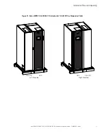
Page 37: ...Installation and Operation Manual P 164000370 Rev 04 29 Figure 11 93PM 50 kW SIAC T or 93PM 50 kW SIAC TB attached to 50 kW UPS as Shipped on Pallet SIAC T UPS UPS SIAC T or SIAC TB or SIAC TB Left Mounted Right Mounted Installation Plan and Unpacking ...

Page 38: ...nd 50 100 kW SIAC TB Installation and Operation Manual P 164000370 Rev 04 Figure 12 Eaton 93PM 100 kW SIAC T attached to 100 kW UPS as Shipped on Pallet SIAC T UPS UPS SIAC T Left Mounted Right Mounted Installation Plan and Unpacking ...

Page 39: ...0 100 kW SIAC TB Installation and Operation Manual P 164000370 Rev 04 31 Figure 13 Eaton 93PM 100 kW SIAC TB attached to 100 kW UPS as Shipped on Pallet SIAC TB UPS UPS SIAC TB Left Mounted Right Mounted Installation Plan and Unpacking ...

Page 40: ...32 Eaton 93PM 50 100 kW SIAC T and 50 100 kW SIAC TB Installation and Operation Manual P 164000370 Rev 04 Installation Plan and Unpacking ...

Page 41: ... cabinets at the factory for use in a two UPS parallel system Refer to the applicable Eaton 93PM UPS Installation and Operation manual listed in paragraph 1 7 For More Information for unloading and mechanical installation instructions NOTE The SIAC T or SIAC TB is attached to and directly integrated with one of the UPS cabinets at the factory for use in a two UPS parallel system The SIAC T and SIA...

Page 42: ...formation for wiring access information and UPS cabinet terminal locations 5 Connect the MOB phase wiring from the SIAC T or SIAC TB to the UPS power terminals Follow the cable phase and neutral designations marked on the cables to connect the cables to the correct terminals Refer to the applicable Eaton 93PM UPS Installation and Operation manual listed in paragraph 1 7 For More Information for UP...

Page 43: ...ting on the SIAC T Install the conduit plate and install all conduit runs into the plate 6 Route the critical load output cables phase A B and C and Ground through the conduit on the bottom of the SIAC T to the SIAC T terminals See Figure 15 for SIAC T wiring access information and Figure 16 for terminal locations 7 Connect phase A B and C and Ground output power wiring from the SIAC T output term...

Page 44: ...al P 164000370 Rev 04 Figure 15 93PM 50 kW SIAC T 93PM 50 kW SIAC TB and 93PM 100 kW SIAC T Conduit Landing Wire Entry Locations Top Entry Conduit Landing Remove plate to drill or punch conduit holes Bottom Entry Conduit Landing Remove plate to drill or punch conduit holes Installation ...

Page 45: ...164000370 Rev 04 37 Figure 16 93PM 50 kW SIAC T and 93PM 100 kW SIAC T Output Power and Ground Terminal Locations AC Output to Critcal Load A B C SIAC T with MIS SIAC T without MIS Front Front AC Output to Critcal Load A B C Ground Ground Ground Terminals Terminals Terminals Installation ...

Page 46: ... and 50 100 kW SIAC TB Installation and Operation Manual P 164000370 Rev 04 Figure 17 93PM 50 kW SIAC T and 93PM 100 kW SIAC T with MIS Output Power Terminal Detail MIS Phase A Phase C Phase B AC Output to Critical Load Installation ...

Page 47: ... holes in the top cover prior to mounting on the SIAC TB Install the top conduit plate and install all conduit runs into the top cover 3 Route the maintenance bypass input and critical load output cables phase A B and C and Ground through the conduit on the top of the SIAC TB to the SIAC TB terminals See Figure 15 or Figure 19 for SIAC TB wiring access information and Figure 20 or Figure 21 for te...

Page 48: ...or SIAC TB wiring and termination requirements Refer to the Eaton 93PM Integrated Accessory Cabinet Distribution 50 kW 100 kW 150 kW and 200 kW IAC D Installation and Operation Manual listed in paragraph 1 7 For More Information for conduit and terminal locations and termination requirements For a detailed view of the SIAC TB terminals see Figure 23 or Figure 24 9 Route and connect ground wiring b...

Page 49: ...Operation Manual P 164000370 Rev 04 41 Figure 19 93PM 100 kW SIAC TB Conduit Landing Wire Entry Locations Top Entry Conduit Landing Remove plate to drill or punch conduit holes NOTE Bottom Entry Conduit Landing Remove plate to drill or punch conduit holes Installation ...

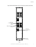
Page 50: ...on and Operation Manual P 164000370 Rev 04 Figure 20 93PM 50 kW SIAC TB Bypass Input Power Output Power and Ground Terminal Locations AC Input to Maintenance Bypass A B C Maintenance Bypass Breaker AC Output to Critcal Load A B C Ground Terminals Front Installation ...

Page 51: ...nd Operation Manual P 164000370 Rev 04 43 Figure 21 93PM 100 kW SIAC TB Bypass Input Power Output Power and Ground Terminal Locations Front AC Input to Maintenance Bypass A B C Maintenance Bypass Breaker AC Output to Critcal Load A B C Ground Terminals Installation ...

Page 52: ...nd 50 100 kW SIAC TB Installation and Operation Manual P 164000370 Rev 04 Figure 22 93PM 50 kW SIAC TB and 93PM 100 kW SIAC TB Bypass Input Power Terminal Detail MBP Phase A Phase C Phase B AC Input to Maimtenance Bypass Installation ...

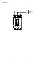
Page 53: ...peration Manual P 164000370 Rev 04 45 Figure 23 93PM 50 kW SIAC TB Output Power Terminal Detail Phase A Phase C Phase B AC Output to Critical Load Figure 24 93PM 100 kW SIAC TB Output Power Terminal Detail Phase A Phase C Phase B AC Output to Critical Load Installation ...

Page 54: ...rst UPS cabinet interface terminals through the upper SIAC T or SIAC TB and first UPS inter cabinet wiring access pass through See Figure 14 for wiring access information and Figure 25 for SIAC T or Figure 27 or Figure 28 for SIAC TB interface terminal locations Refer to the applicable Eaton 93PM UPS Installation and Operation manual listed in paragraph 1 7 For More Information for wiring access i...

Page 55: ... and route the cable from the SIAC TB through the lower SIAC TB and second UPS inter cabinet wiring access pass through see Figure 14 to the second UPS MBP interface terminals See Figure 31 for UPS cabinet MBP interface terminal location Refer to the applicable Eaton 93PM UPS Installation and Operation manual listed in paragraph 1 7 For More Information for wiring access information 12 Connect the...

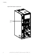
Page 56: ...48 Eaton 93PM 50 100 kW SIAC T and 50 100 kW SIAC TB Installation and Operation Manual P 164000370 Rev 04 Figure 25 SIAC T Interface Terminal Location Interface Terminal Block Installation ...

Page 57: ...2 Aux 1 NC MOB 2 Aux 1 COM MOB 2 Aux 2 NO Pull Chain Common Factory Interface Wiring To MOB Auxiliary Contacts UPS 1 Building Alarm UPS 1 Building Alarm Return UPS 1 Pull Chain UPS 1 Pull Chain COM UPS 2 Building Alarm UPS 2 Building Alarm Return UPS 2 Pull Chain UPS 2 Pull Chain COM 2 PoleTerminal Block Jumper Customer Interface Wiring NOTE UPS building alarm signals are customer programmable Cus...

Page 58: ... Eaton 93PM 50 100 kW SIAC T and 50 100 kW SIAC TB Installation and Operation Manual P 164000370 Rev 04 Figure 27 Eaton 93PM 50 kW SIAC TB Interface Terminal Location Interface Terminal Block Installation ...

Page 59: ...Eaton 93PM 50 100 kW SIAC T and 50 100 kW SIAC TB Installation and Operation Manual P 164000370 Rev 04 51 Figure 28 93PM 100 kW SIAC TB Interface Terminal Location Interface Terminal Block Installation ...

Page 60: ...Chain UPS 1 Pull Chain COM UPS 2 Building Alarm UPS 2 Building Alarm Return UPS 2 Pull Chain UPS 2 Pull Chain COM UPS 1 MBP Return UPS 2 MBP Return UPS 1 MBP Detect UPS 2 MBP Detect 2 PoleTerminal Block Jumper Customer Interface Wiring NOTE UPS building alarm signals are customer programmable Customer interface wiring for the SIAC TB MOBs assumes that the UPS Building Alarm is programmed to monito...

Page 61: ...tacts are closed when MOB 2 is open TB1 10 MOB2 Aux 1 COM UPS 2 Building Alarm Return TB1 11 MOB2 Aux 2 NO UPS 2 Pull Chain Terminal 1 Output UPS 2 Pull Chain Backup control for parallel operation TB1 12 Pull Chain Common UPS 2 Pull Chain Return Terminal 2 Output UPS 2Pull Chain Common NOTE UPS building alarm signals are customer programmable Customer interface wiring for the SIAC T MOBs assumes t...

Page 62: ...ontrol for parallel operation TB1 12 Pull Chain Common UPS 2 Pull Chain Return Terminal 2 Output UPS 2Pull Chain Common TB2 1 MBP Aux 1 COM UPS 1 MBP Output Normally Open NO contact used to indicate whether the MBP is closed and the UPS system is on maintenance bypass Contacts are closed when the MBP is closed TB2 3 MBP Aux 1 NC UPS 1MBP Return TB2 2 MBP Aux 2 COM UPS 2 MBP Output Normally Open NO...

Page 63: ...AUX 2 1 2 3 4 5 6 7 8 9 10 UPS 1 Building Alarm TB 1 2 3 4 5 6 7 8 9 10 UPS 2 Building Alarm TB Pull Chain Twisted Pair Twisted Pair 5 6 7 8 9 10 11 12 1 2 BA 1 BA 2 BA 3 BA 4 BA 5 BA 1 BA 2 BA 3 BA 4 BA 5 NOTE 1 MOB and pull chain connections between the UPS and MOB Aux contacts require twisted pair wire NOTE 2 NC and NO designations on MOB AUX contacts are defined with breaker in OFF open positi...

Page 64: ...56 Eaton 93PM 50 100 kW SIAC T and 50 100 kW SIAC TB Installation and Operation Manual P 164000370 Rev 04 Figure 31 UPS MBP Interface Terminal Location MBP Interface Terminal Block Installation ...

Page 65: ... tu up p Startup and operational checks must be performed by an authorized Eaton Customer Service Engineer or the warranty terms specified on the product s resources page become void See Chapter 9 Warranty for details This service is offered as part of the sales contract for the UPS Contact an Eaton service representative in advance a minimum two week notice is required to reserve a preferred star...

Page 66: ...ave been completed NOTE The Installation Checklist MUST be completed prior to starting the UPS system for the first time Installation Checklist o All packing materials and restraints have been removed from each cabinet o The UPS and SIAC T or SIAC TB are installed on a level floor in a suitable location for computer or electronic equipment o All conduits and cables are properly routed between the ...

Page 67: ..._______________________________________ _________________________________________________________________________ _________________________________________________________________________ _________________________________________________________________________ _________________________________________________________________________ ________________________________________________________________...

Page 68: ...60 Eaton 93PM 50 100 kW SIAC T and 50 100 kW SIAC TB Installation and Operation Manual P 164000370 Rev 04 Installation ...

Page 69: ...34 show the simplified internal structure of the Sidecar Integrated Accessory Cabinet Ties SIAC T and Figure 35 shows the simplified internal structure of the Sidecar Integrated Accessory Cabinet Tie Bypasss SIAC TB Figure 33 Two Breaker no MIS Sidecar Integrated Accessory Cabinet Tie SIAC T Internal Oneline 100 kW SIAC T 480V 3 Phase from UPS 1 Output 480V 3 Phase from UPS 2 Output MOB 1 MOB 2 Ti...

Page 70: ...e from UPS 1 Output 480V 3 Phase from UPS 2 Output MOB 1 MOB 2 Tie Bus MIS 480V 3 Phase SIAC T Output 50 kW and A B A Figure 35 Four Breaker with MIS and MBP Sidecar Integrated Accessory Cabinet Tie Bypass SIAC TB Internal Oneline 100 kW SIAC TB 480V 3 Phase from UPS 1 Output 480V 3 Phase from UPS 2 Output 480V 3 Phase Bypass Input MOB 1 MOB 2 Tie Bus MIS MBP Load Bus 480V 3 Phase SIAC TB Output 5...

Page 71: ...mplified internal structure of the UPS and SIAC T and SIAC TB NOTE The onelines in Figure 5 4 through Figure 5 6 do not show each UPM in each UPS in detail but represents each UPS in the parallel system The internal structure of each UPS is shown in more detail in the applicable Eaton 93PM UPS Installation and Operation manual listed in paragraph 1 7 For More Information Onelines and Schematics ...

Page 72: ...E8 Module Output Breaker 1 MOB 1 Bypass Switchgear Static Swtich Fuse Optional Single Feed Jumper Module Output Breaker 2 MOB 2 E4 E5 E4 E5 AC Input to UPS 1 Rectifier 3 Wire A B C Rotation AC Input to UPS 1 Bypass 3 Wire A B C Rotation Dual Feed AC Input to UPS 2 Bypass 3 Wire A B C Rotation Dual Feed AC Input to UPS 2 Rectifier 3 Wire A B C Rotation AC Output to Critical Load E1 E2 E3 E6 E7 E8 E...

Page 73: ... MIS E9 E10 E11 AC Output to Critical Load AC Input to UPS 1 Rectifier 3 Wire A B C Rotation AC Input to UPS 1 Bypass 3 Wire A B C Rotation Dual Feed E1 E2 E3 A A B E6 E7 E8 Module Output Breaker 1 MOB 1 Bypass Switchgear Static Swtich Fuse Optional Single Feed Jumper Module Output Breaker 2 MOB 2 E1 E2 E3 E6 E7 E8 E9 E10 E11 E4 E5 E4 E5 Not supplied with the UPS EXTERNAL BATTERY CABINET Battery B...

Page 74: ...se Optional Single Feed Jumper Module Output Breaker 2 MOB 2 E4 E5 E4 E5 AC Input to UPS 1 Rectifier 3 Wire A B C Rotation AC Input to UPS 1 Bypass 3 Wire A B C Rotation Dual Feed AC Input to UPS 2 Bypass 3 Wire A B C Rotation Dual Feed AC Input to UPS 2 Rectifier 3 Wire A B C Rotation AC Output to Critical Load E1 E2 E3 E6 E7 E8 E9 E10 E11 Not supplied with the UPS EXTERNAL BATTERY CABINET Batter...

Page 75: ...out MIS Schematic MOB1 MOB2 6 5 7 1 8 10 9 11 2 12 MOB1 NC UPS1 BLDG ALARM MOB1 COM UPS1 BLDG ALARM MOB1 NO UPS1 PULL CHAIN MOB1 GND UPS1 PULL CHAIN MOB2 NC UPS2 BLDG ALARM MOB2 COM UPS2 BLDG ALARM MOB2 NO UPS2 PULL CHAIN MOB2 GND UPS2 PULL CHAIN TO LOAD DISTRIBUTION TIE BUS A TIE BUS B TIE BUS C 1 1 2 0 MIS 2 0 1 1 FROM UPS1 OUTPUT FROM UPS2 OUTPUT FROM UPS1 GROUND FROM UPS2 GROUND TO LOAD GROUND...

Page 76: ...NC UPS1 BLDG ALARM MOB1 COM UPS1 BLDG ALARM MOB1 NO UPS1 PULL CHAIN MOB1 GND UPS1 PULL CHAIN MOB2 NC UPS2 BLDG ALARM MOB2 COM UPS2 BLDG ALARM MOB2 NO UPS2 PULL CHAIN MOB2 GND UPS2 PULL CHAIN TO LOAD DISTRIBUTION TIE BUS A TIE BUS B TIE BUS C 1 1 2 0 FROM UPS1 OUTPUT FROM UPS2 OUTPUT FROM UPS1 GROUND FROM UPS2 GROUND TO LOAD GROUND FROM BUILDING GROUND G G G TBG G EATON 93PM 50 kW AND 100 kW SIAC T...

Page 77: ...COM UPS1 MBS_GND MBP NC UPS1 MBS_DET MBP COM UPS2 MBS_GND MBP NC UPS2 MBS_DET MOB2 NC UPS2 BLDG ALARM MOB2 COM UPS2 BLDG ALARM MOB2 NO UPS2 PULL CHAIN MOB2 GND UPS2 PULL CHAIN TO LOAD DISTRIBUTION BYPASS INPUT TIE BUS A TIE BUS B TIE BUS C 1 1 2 0 LOAD BUS A LOAD BUS B LOAD BUS C MBP 2 0 1 1 MIS 2 0 1 1 1 1 2 0 FROM UPS1 OUTPUT FROM UPS2 OUTPUT FROM UPS1 GROUND FROM UPS2 GROUND TO LOAD GROUND FROM...

Page 78: ...70 Eaton 93PM 50 100 kW SIAC T and 50 100 kW SIAC TB Installation and Operation Manual P 164000370 Rev 04 Onelines and Schematics ...

Page 79: ...rc cu uiit t B Br re ea ak ke er rs s Figure 42 identifies and shows the location of the circuit breakers in the SIAC T The descriptions provide a brief overview of the SIAC T breaker use Module Output Breaker The Module Output Breaker MOB controls the output from the UPS modules and enable two modules to be paralleled together for redundancy or increased capacity Maintenance Isolation Breaker The...

Page 80: ...n Manual P 164000370 Rev 04 Figure 42 93PM 50 kW SIAC T or 93PM 100 kW SIAC T Breakers MOB 1 MOB 2 MIS Optional NOTE The 93PM 100 kW UPS is shown with a left mounted SIAC T A UPS with a right mounted SIAC T is the mirror image SIAC T UPS SIAC T and SIAC TB Operating Instructions ...

Page 81: ... screw for later use 2 Close the SIAC TB bypass input feeder circuit breaker 3 Verify that the SIAC TB circuit breakers are set as follows see Figure 44 or Figure 44 for breaker locations MOB 1 CLOSED MOB 2 CLOSED MBP OPEN MIS CLOSED 4 Start the UPS Refer to the applicable Eaton 93PM UPS Installation and Operation manual listed in paragraph 1 7 For More Information for UPS operating procedures 5 R...

Page 82: ...on Manual P 164000370 Rev 04 Figure 43 93PM 50 kW SIAC TB Breakers MOB 1 MOB 2 MBP Bypass Interlock Plate MIS SIAC TB UPS NOTE The 93PM 50 kW UPS is shown with a left mounted SIAC TB A UPS with a right mounted SIAC TB is the mirror image SIAC T and SIAC TB Operating Instructions ...

Page 83: ...TB Breakers MOB 1 MOB 2 MBP Bypass Interlock Plate MIS NOTE The 93PM 100 kW UPS is shown with a left mounted SIAC TB A UPS with a right mounted SIAC TB is the mirror image SIAC TB UPS CAUTION Failure to close the MBP before opening the MIS will result in the loss of power to the critical load SIAC T and SIAC TB Operating Instructions ...

Page 84: ...ailure to follow this transfer sequence may cause loss of power to loads To transfer the load from maintenance 1 Remove the screw securing the bottom of the SIAC TB front panel Lift the panel straight up to remove it from the panel hanger bracket at the top of the cabinet Retain screw for later use 2 Close the MOBs 3 Start the UPS in bypass mode Refer to the applicable Eaton 93PM UPS Installation ...

Page 85: ...miin ng g P Pr re ev ve en nt tiiv ve e M Ma aiin nt te en na an nc ce e The UPS system requires very little preventive maintenance However the system should be inspected periodically to verify that the units are operating normally Record maintenance results and any corrective actions in a suitable log 7 7 2 2 1 1 D DA AI IL LY Y M Ma aiin nt te en na an nc ce e Perform the following steps daily 1...

Page 86: ...ce e T Tr ra aiin niin ng g A basic training course available from Eaton gives you a competent working knowledge of the UPS system operation and teaches you how to perform first level corrective maintenance For more information about training and other services contact the Customer Reliability Center see paragraph 1 8 Getting Help Maintenance ...

Page 87: ...egrated Accessory Cabinet Tie SIAC T for the Eaton 93PM 100 kW UPS Eaton 93PM 100 kW SIAC TB Sidecar Integrated Accessory Cabinet Tie Bypass SIAC TB for the Eaton 93PM 100 kWUPS 8 8 2 2 S Sp pe ec ciif fiic ca at tiio on ns s The following sections detail the input output and environmental and safety specifications for the SIACs 8 8 2 2 1 1 I In np pu ut t Operating Input Voltage and Frequency 480...

Page 88: ...tallation and Operation Manual P 164000370 Rev 04 Ventilation Convection Relative Humidity operating and storage 5 to 95 maximum noncondensing Acoustical Noise Not applicable Safety Conformance UL1778 5th edition Agency Markings cULus Product Specifications ...

Page 89: ...e click on the link or copy the address to download from the Eaton website UPS Product Warranty https www eaton com content dam eaton products backup power ups surge it power distribution backup power ups portfolio eaton three phase ups warranty pdf EQUIPMENT REGISTRATION Please visit www eaton com pq register to register your new Eaton UPS Eaton UPS Accessory Model Number Serial Number ...

Page 90: ...P 16400037004 P 164000370 04 ...

Reviews: