25-75 kW
User's and Installation Guide
36
4
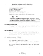
UPS SYSTEM INSTAllATION
The customer has to supply the wiring to connect the UPS to the local power source. The electrical
installation procedure is described in the following section. The installation inspection and the initial start-up
of the UPS and installing an extra battery cabinet must be carried out by qualified service personnel such as a
licensed service engineer from the manufacturer or from an agent authorized by the manufacturer.
WARNING
Physical injury or death may follow, or damage may occur to the UPS or the load equipment if these instructions
are ignored.
4.1 Steps to Install the UPS
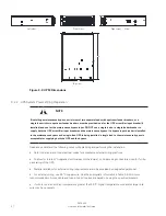
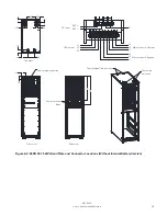
93PR UPS can only support top cable entry. The customer power wires and control wiring can pass through
openings on the top rear of UPS cabinet connect to UPS terminal blocks at rear of UPS, see Figure 4-1: 93PR
25-75 kW Gland Plate and Connector Locations (With Internal Battery Version) and Figure 4-2: 93PR 25-75
kW Gland Plate and Connector Locations (Without Internal Battery Version)
1. Unlocked the door lock to open the front or rear door.
1. Remove the safety plate from the power terminal block.
2. At the top of UPS, there is enough holes for customer’s cables.
3. Install all the cables to UPS terminal block from the cable conduit.
4. Route and connect power cables.
5. When all cable connection is complete, reinstall safety shield panels.
6. Close the door and secure with latch.
7. If installing a parallel system, repeat the above steps to all units in the system.
Summary of Contents for 93PR 25(75)
Page 1: ...User s and Installation Guide Eaton 93PR UPS 25 75 kW ...
Page 2: ......
Page 3: ...Eaton 93PR UPS 25 75 kW User s and Installation Guide ...
Page 96: ......
Page 97: ......
Page 98: ...614 02087 00 ...

