25-75 kW
User's and Installation Guide
59
60
30-200 kW
P-164000249
User's and Installation Guide
Revision 2
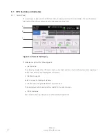
6.1.2 Status indicators
The four symbols below the display are status indicators. They are colored light emitting diode (LED)
lamps, and they work in conjunction with the alarm horn to let you know the operating status of the
UPS.
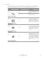
Indicator
Status
Description
On
The UPS is operating normally
and supplying power to the crit-
ical load.
Green
Figure 6-2: Green symbol
Off
The UPS is turned off.
Yellow
Figure 6-3: Yellow symbol —
battery mode
On
The UPS is in Battery mode.
Because Battery mode is a nor-
mal condition of the UPS, the
Normal indicator also remains
illuminated.
P-164000249
Revision 2
6.1.2 Status indicators
The four symbols below the display are status indicators. They are colored light emitting diode (LED)
lamps, and they work in conjunction with the alarm horn to let you know the operating status of the
UPS.
Indicator
Status
Description
On
The UPS is operating normally
and supplying power to the crit-
ical load.
Green
Figure 6-2: Green symbol
Off
The UPS is turned off.
Yellow
Figure 6-3: Yellow symbol —
battery mode
On
The UPS is in Battery mode.
Because Battery mode is a nor-
mal condition of the UPS, the
Normal indicator also remains
illuminated.
Yellow
Figure 6-4: Yellow symbol —
bypass mode
On
The UPS is in Bypass mode.
The critical load is supported
by the bypass source. The Nor-
mal indicator is not illuminated
when the system is in Bypass
mode.
Red
Figure 6-5: Red symbol
On
The UPS has an active alarm
and requires immediate atten-
tion. The screen shows the
highest priority active alarms.
All alarms are accompanied by
an audible horn. To silence the
horn, press any control panel
button once. The Alarm indica-
tor may be illuminated along
with other indicators.
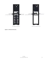
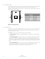
6.1.3 UPS Status Lights
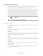
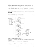
The LED Power Show (LPS) consists of two rows of LEDs located on the left and right sides of the UPS cab-
net door. The LEDs are of red, green and yellow (RGY). The color of the LEDs is used to show the
condition of the UPS. Only one color is shown at one time. The most urgent condition is always shown. The
priority rank is Red,Yellow and Green.
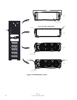
Figure 6-7: UPS Status lights
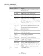
6.1.4 System Events
incoming utility power. In Battery or Bypass Modes, the UPS may issue alarms to let you know exactly what
event caused the change from Double Conversion Mode. System events on the UPS can be indicated by
horns, lights, messages, or all three.
Select
logs
from the main menu screen to look at any currently active events.
•
System Event Horn
- The system event horn beeps to alert an operator that an event needing atten-
tion is taking place.
•
System Event Indicators
- The status indicators on the UPS control panel and the event horn let you
know when the UPS system is operating in any mode other than Double Conversion Mode. Only the
Normal indicator is visible during normal UPS system operation. The other indicators illuminate to indicate
alarms or events. When an alarm occurs, first check these indicators to see what type of event has taken
place.
•
System Event Messages
- When a system event occurs, a message appears in the status bar of the
display. This message is also written to the Active Events log. Some notices and alarms may be
accompanied by an audible horn. To silence the horn, press any button once.
UPS Status
Color lEd Indicator
Operating normally
Green lighting
In Battery Mode
Green twinkle
In Bypass Mode
Yellow lighting
Fault or Alarm
Red lighting
LPS
LPS
Summary of Contents for 93PR 25(75)
Page 1: ...User s and Installation Guide Eaton 93PR UPS 25 75 kW ...
Page 2: ......
Page 3: ...Eaton 93PR UPS 25 75 kW User s and Installation Guide ...
Page 96: ......
Page 97: ......
Page 98: ...614 02087 00 ...

