70
Copyright © 2021 Eaton Corporation plc. All rights reserved.
4.10. Installing Interface Connections
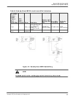
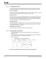
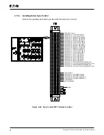
93PR UPS contains a total of five (5) signal input connectors for customers which can be used for
giving remote control commands to the UPS. Customer interface connector CN5 can be used forthese
purposes. Each input is a dry relay contact input and requires two wire signaling. None of the inputs are
pre-programmed but need to be separately programmed by qualified service personnel.
When using an external battery system (either the original 93PR battery cabinet or a customer sourced
battery cabinet/rack), external signaling wiring is recommended to be connected.
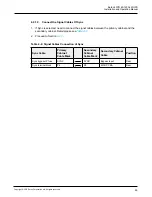
One (1) general alarm relay output is also on the front panel. This output is either normally open (NO) or
normally closed (NC). Polarity selection is made with wiring connection.
By default, the general alarm relay activates when a system alarm is active, that is, any ALARM
condition in the system is active. Alternatively, it can be activated with any particular event but this must
be programmed separately by qualified service personnel. The alarm relay is designed for signal level
(ELV or SELV) voltages only, not for utility use. For higher signaling circuit voltage requirements, please
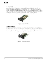
use Industrial Relay Adapter in Mini-slot.
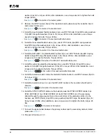
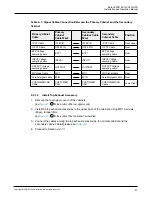
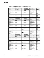
4.10.1. Installing Customer Input Signals Interface
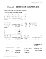
Communication Interfaces. Tie points with strain relief
for communication cables are located on the right and left side of the cable conduit.
Signal inputs can be configured to different functions. Normally these functions are either
informative (for example “On Generator”) or functional (for example remote “Go to bypass”
command).
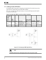
4.10.2. External Battery Breaker Wiring Interface
When using the original battery cabinet from the Eaton, the battery breaker interface wiring is
provided with the cabinet. Connecting it requires only routing the wires from the cabinet to the
bottom section of the UPS.
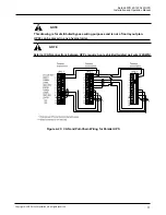
When using third party battery system, the breaker must be equipped with auxiliary signal and
should have a 48V Shunt release for remote opening of the breaker, when needed.
Wire entry for battery breaker signal wiring is located on the top of the UPS cabinet. The wire
can pass through the top of UPS cabinet and locked to external battery breaker control terminal
at the front of the module (see
). Pin 1 and 2 of the terminal are for signal connection
of battery breaker Shunt release control, and Pin 3 and 4 are for Signal connection of battery
breaker Aux contact detection.
Summary of Contents for 93PR Series
Page 1: ...60 1200 kW Installation and Operation Manual Eaton 93PR UPS ...
Page 2: ......
Page 142: ......
Page 143: ...614 40061 01 ...

