Eaton 93PR 60-1200 kW UPS
Installation and Operation Manual
71
Copyright © 2021 Eaton Corporation plc. All rights reserved.
4.10.3. Relay Output Interface Connections
The general alarm relay is a dry relay signal output. The relay can be used for informing the
operators about UPS alarm conditions, for example through a building management system.
By default, the relay is configured to activate when the UPS general alarm is active, that is, any
event having ALARM status is active. The relay can also be configured to activate by some
other event but this needs to be done by authorized service.
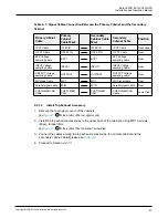
Relay signal wiring can be installed only through the signal cabling canal, from back to front, on
the top section of the UPS.
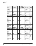
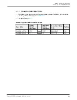
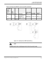
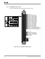
Table 4-6: Dry Contact Output Terminal
User logical selection
Terminal pins connection
shows on HMI
Note
NO
2-3
Pin1 disconnection
NC
1-3
Pin2 disconnection
4.10.4. Mini-slot Interface Connections
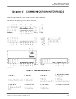
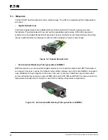
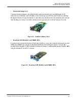
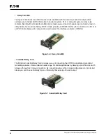
For Mini-slot accessories and communication devices selection see
INTERFACES. For installation and setup of a Mini-slot card, please contact your Eaton
representative.
To install wiring to connections:
1. If not already installed, install the LAN and telephone drops.
2. Open the front door of the UPS.
3. Remove the particular Mini-slot cover plate by removing the two screws securing the plate
and install the device by pushing it all the way in.
4. Secure the Mini-slot communication device with two screws.
5. Route and install the LAN, telephone, and other cables to the appropriate Mini-slot cards.
Cable route is through the signal cable canal, on top section of the UPS.
6. Refer to the manual supplied with the Mini-slot card for operator instructions.
7. When all wiring is completed, close the front door and secure the latch.
4.10.5. Installing Signal Interface Connections In Parallel System
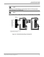
Installation of signal interface connections in parallel system is done by following the
aforementioned instructions. Signal inputs can be paralleled between the units, that is, the same
contact can be used for several units’ signal input signaling. This concerns also the EPO-signal.
Summary of Contents for 93PR Series
Page 1: ...60 1200 kW Installation and Operation Manual Eaton 93PR UPS ...
Page 2: ......
Page 142: ......
Page 143: ...614 40061 01 ...

