Heat rejection
(BTU/h x 1,000)
Heat rejection
(kW)
10 kW
1.46
0.4
15 kW
2.19
0.6
20 kW
2.92
0.9
30 kW
4.38
1.3
40 kW
5.84
1.7
Battery locations and enclosures must be ventilated to maintain the hydrogen
concentration below the 4%
vol
safety limit. Adequate air ventilation must be
provided to locations where the UPS and batteries are located. For the 93PS
UPS 8–20kW with internal batteries, the minimum air flow is 3 m
3
/hour and the
minimum free area of opening for inlet and outlet is 84 cm
2
when natural
ventilation is used. For the 93PS UPS 40 kW, the minimum air flow is 6 m
3
/hour
and the minimum free area of opening for inlet and outlet is 168 cm
2
when
natural ventilation is used. For larger batteries, the ventilation air flow must be
recalculated.
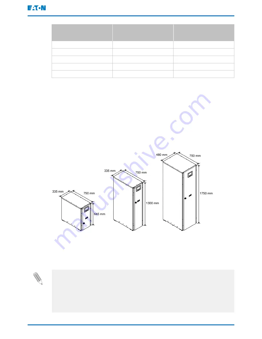
For the dimensions of the 93PS UPS cabinets, see Figure
9
.
Figure 9. The dimensions of the Eaton 93PS UPS 20 kW C-model frame, the 93PS UPS
20 kW frame, and the 93PS UPS 40 kW frame, respectively.
4.3.2
UPS system power wiring preparations
Note: If you are installing a maintenance bypass, provide one of the following:
- a minimum of 2 separate feeds with upstream feeder breakers
- a single feed with 2 upstream feeder breakers: one for the UPS or rectifier
input breaker and one for the maintenance bypass input.
Do not use a single feed or a single feeder breaker to supply
Eaton 93PS UPS 8–40 kW
User's and installation guide
©
Eaton Corporation plc 2016. All rights reserved.
Revision: 003
Document ID: P-164000493
38 (104)


