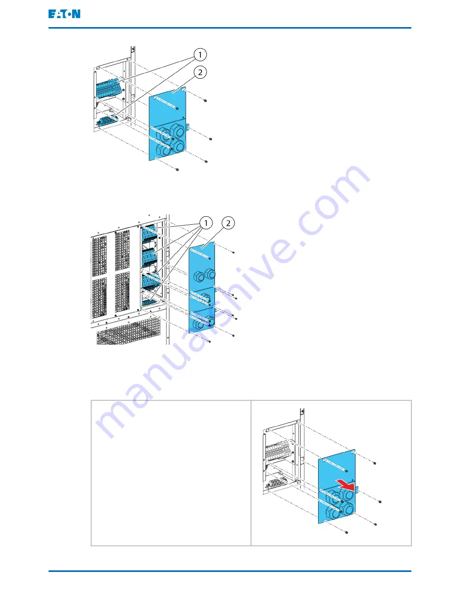
Figure 12. Gland plate and connector locations in the 93PS UPS 20 kW standard and C-
model frames
Figure 13. Gland plate and connector locations in the 93PS UPS 40 kW frame
1
Connectors
2
Gland plate
1.
To gain access to the terminal
blocks, remove the screws
securing the gland plate at the
back of the UPS.
Eaton 93PS UPS 8–40 kW
User's and installation guide
©
Eaton Corporation plc 2016. All rights reserved.
Revision: 003
Document ID: P-164000493
50 (104)


