Page 11
3.3.2
UPS
W
IRING
C
ONNECTION
To make the mains power and load connections,
follow the instructions below:
1. Install a magneto-thermal switch (
63A for 6 & 10kVA
versions, 125A for 15 and 20kVA versions
) with
intervention curve D upstream of the machine (4 poles
for three-phase versions, 2 poles for single-phase
versions).
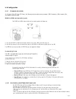
2. The connection terminals to use for the input and output
lines are located on the backpanel. Unscrew the 4
screws located on the sides of the cover (one on each
side, see figure).
3. Remove the backpanel cover (see figure to the side).
Fig.3-3 Wiring connection
S
INGLE
-
PHASE VERSION
(9E6K
I ONLY
)
4.
(SINGLE-PHASE CONNECTION
9E6KI
): use 3 cables with cross-section 6 mm
2
(EARTH, N and L) for the input, and 3
cables with cross-section 6 mm
2
for the output (EARTH, N and L).
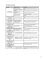
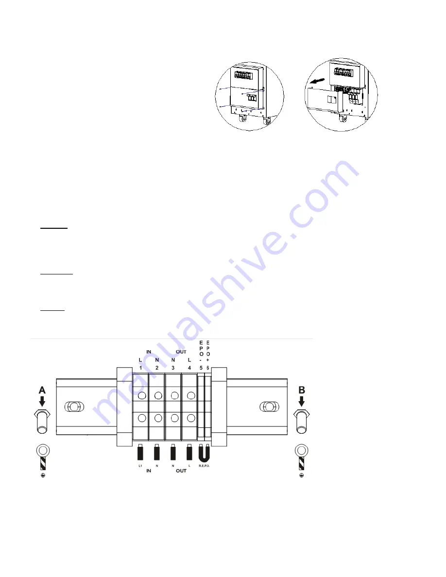
5. Connect the wires to the relative terminals, following exactly the instructions given below:
Input line
a - Make sure that the magneto-thermal switch upstream is open.
b - Connect the earth wire to screw A.
c - Connect the neutral wire to terminal 2.
d - Connect the live wire to terminal 1.
Output line
a - Connect the earth wire to screw B.
b - Connect the neutral wire to terminal 3.
c - Connect the live wire to terminal 4.
R.E.P.O.
a - The REPO connection (between terminal 5 and 6) is normally open. For more information please refer to the REPO section
of this manual
Fig.3-4 6K terminal view
6. Tighten the terminals well, close the backpanel cover and secure it with the screws taken out earlier.
The suggested tighten force is 1.2~1.6Nm.


