Page 16
4.OPERATION
4.1 Display and Buttons
Fig. 4-1 Control Panel
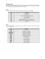
The following tables shows the buttons, LCD indicator and LED indicator status and description:
Table 4-1 Control Buttons Functions
The Button
Function
Illustration
Turn on
If the UPS is in standby or bypass mode, press >2s, the buzzer will beep once, then the UPS
system will be turned on.
Turn off
If the UPS is in line, battery, HE or battery test mode, press >3s, the buzzer will beep once, then
the UPS will be turned off.
Transfer
If the UPS is in fault mode, and the fault cause has disappeared, press >2s, the buzzer will beep
once, fault will be cleared and UPS will turn to standby mode.
Function key
Battery test on line mode,Press the button >2s
Mute: Press the button >2s
Down to next page: Press the button<200ms
Table 4-2 LED indicator
LED name
Colour
Description
Line
Green
It indicates the utility is normal
Battery
Yellow
It indicates the input is connected with battery, and the
input power is supplied from the battery.
Bypass
Yellow
It indicates the UPS is in bypass mode, the load current is
directly supplied from the utility power
Inverter
Green
It indicates that the inverter is OK and the load is supplied
from the inverter.
Note: After UPS power on, all LEDs will be lightened for 2 seconds, and then turn to normal status. When UPS is turning on, 4
LEDs will be lightened one by one until the UPS is turned on successfully.
⊙
:Utility is normal
●: Lightened constantly
★
: Flashing every 4s
◇
: Depended on the fault status
□: Depend on the original display
LED
Line
Battery
Bypass
Inverter
No Output mode
⊙
Bypass mode
●
●
Line mode
●
●
Battery mode
●
●
Battery test mode
★
●
Fault mode
□
◇
Warning
□
□
□
□


